| Author |
Message |
Project_2501

Joined: Jan 31, 2018
Posts: 68
Location: Los Angeles
|
 Posted: Sat Feb 24, 2018 11:22 pm Post subject: Posted: Sat Feb 24, 2018 11:22 pm Post subject:
 MS-20 VCF Stripboard Layout MS-20 VCF Stripboard Layout |
  |
|
I've been looking around for an MS-20 VCF layout for awhile. I've seen acouple but none of them verified or have clear directions, especially on potentiometer wiring. Does anyone have a verified Stripboard layout laying around the drive. That would be beautiful if you post it  |
|
|
Back to top
|
|
 |
favicius
Joined: Apr 10, 2015
Posts: 3
Location: spain
|
| Posted: Thu Mar 01, 2018 10:52 pm Post subject:
|
|
|
Hi, this layout is verified.

Enjoy |
|
|
Back to top
|
|
|
Project_2501
Joined: Jan 31, 2018
Posts: 68
Location: Los Angeles
|
| Posted: Sat Mar 03, 2018 2:02 pm Post subject:
|
|
|
Thank you so much for posting this! 
Does anyone know the Res. Potentiometer value? 100k log maybe?
Also, is that switch a DPDT ON-OFF-ON switch? Is that for LP/HP? [/b]
Last edited by Project_2501 on Mon Mar 05, 2018 2:41 pm; edited 2 times in total |
|
|
Back to top
|
|
|
gabbagabi

Joined: Nov 29, 2008
Posts: 652
Location: Berlin by n8
Audio files: 23
|
| Posted: Sun Mar 04, 2018 1:14 am Post subject:
|
|
|
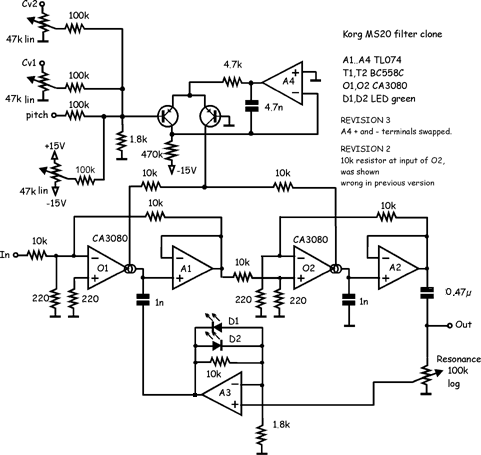
looks like this is the "Late MS-20 Filter" from Rene Schmitz
just search for it |
|
|
Back to top
|
|
|
wackelpeter
Joined: May 05, 2013
Posts: 461
Location: germany
Audio files: 10
|
| Posted: Sun Mar 04, 2018 4:13 am Post subject:
|
|
|
In the original schematic the reso pot is 10k. However i once build this and made a dual Version, both switchable between LPF and HPF and able to work as two separate VCF's and wasn't really happy with my results.
A few weeks ago i decided to stick rather to the original schematics and replace all different values and add the few missing components except keeping the Op-Amp buffer and well i think ti does sound much better now.
Perhaps add a input attentuator for the signal in and a trim each for resonance and center frequency.
btw. the above posted stripboard layout can be improved.
First add some 10R resistors and decoupling caps on the power rails, also use decoupling caps for the LM13700 and place them as close to it's rails as possible. perhaps move that one resistor leg away from the bottom of the IC or move it more to the side and cut the trace behind it and then make this line a gnd line so you can place the caps really close, going from 6 and 11 to the trace below the IC.
Also i see there is a flaw in this layout, on the OP-amp pin 1and 2 (the Op amp in the resonance Feedback path) the diodes (original 6 diodes, 3 in each directing in series or instead 2 LEDs) and the feedback resistor (original schematic 10k) seem to be off, they should sit between 1 and 2 and not connected to -12V. Perhaps you should have a look at the original schematic too, and also there's somewhere in the net the Adaption of Scott Stites with the switched variant, were you can change between LPF/HPF mode.
_________________
https://soundcloud.com/bastian-j |
|
|
Back to top
|
|
|
Project_2501
Joined: Jan 31, 2018
Posts: 68
Location: Los Angeles
|
| Posted: Mon Mar 05, 2018 3:29 pm Post subject:
|
|
|
| wackelpeter wrote: |
First add some 10R resistors and decoupling caps on the power rails, also use decoupling caps for the LM13700 and place them as close to it's rails as possible. perhaps move that one resistor leg away from the bottom of the IC or move it more to the side and cut the trace behind it and then make this line a gnd line so you can place the caps really close, going from 6 and 11 to the trace below the IC.
Also i see there is a flaw in this layout, on the OP-amp pin 1and 2 (the Op amp in the resonance Feedback path) the diodes (original 6 diodes, 3 in each directing in series or instead 2 LEDs) and the feedback resistor (original schematic 10k) seem to be off, they should sit between 1 and 2 and not connected to -12V. Perhaps you should have a look at the original schematic too, and also there's somewhere in the net the Adaption of Scott Stites with the switched variant, were you can change between LPF/HPF mode. |
Thanks for the upgrades. I'll give em a try when I get there.
The Bottom Resistors under the IC isn't there. I remember seeing this same layout somewhere with the cutouts and bottom resistors, but lost that pic 
Is Res 2 suppose to be there? Don't see it.
I found the later layout without that Switch. Also, I went digging and found the schematic, or I think I found it.
Side note: Bastian J., Love your stuff, I just spent sometime on your soundcloud 
| Description: |
|
| Filesize: |
15.82 KB |
| Viewed: |
19056 Time(s) |
|
|
|
|
Back to top
|
|
|
wackelpeter
Joined: May 05, 2013
Posts: 461
Location: germany
Audio files: 10
|
| Posted: Tue Mar 06, 2018 9:39 am Post subject:
|
|
|
Hi, thanks for finding those kind words for my attempts at being somewhat musical
My neighbours think otherwise...
i'm not sure what you mean with the bottom resistor.
what i meant, was moving R18 (10k) the resistor for the Signal Input to the left on the board, then cut the trace right to it (on the leg at the bottom and not that one going to the LM13700), hook te inputwhich is here labelled as SW B1 to the hard left on that race and then you would have the rest of the trace "free" and could use it as a ground line to connect the decoupling caps to the IC, which are included in that design already even if in a bit more distance, but what i ignored in first instance or simply haven't seen first.
Maybe to give you a hint, what i meant can bee seen here:
http://electro-music.com/forum/phpbb-files/121vcf_676.png
That's the only layout i made, it took as nearly as Long as doing the stripboard so i decided to move along my usual way and just solder my way through the schematics.
Further thought on reducing the signal path for the Input is, if you Keep your signal lines that Long and especially direct between the rails, this could result in crosstalk of your signal to your power rails... so it's best to Keep them as short as possible.
Well the third leg of the resonance pot goes straight to gnd... not drawn there but can bee seen in the schematic you've posted.
What i said Looks false is what is in the schematic A3 which is in the layout the upper left OPamp of the LF347. You see the spacing is incorrect for the diodes, moved on trace up.
Here's a link to the site of Scott Stites Version:
http://www.birthofasynth.com/Scott_Stites/Pages/dualms20_main.html#Independent_Mode_Operation
I strongly recommend to try and use his Mutant vactrol VCF you can build These also as separate VCF's and only having the BPF Version so far, this one kicks asses.
and here's a link to the original MS20 schematic:
http://machines.hyperreal.org/manufacturers/Korg/MS-synths/schematics/KLM-307.GIF
Note, that in the MS20 the Signal goes first into the HPF and then into the LPF, both are almost the same except a few minor changes, they mostly differ at the Point were you insert the Audio signal.
You can build also a single VCF of it were you can Switch the unit between HPF and LPF, what i have done.... build 2 of them so i can resemble the original signal flow or let them act as 2 separate VCF's.
Cheers Bastian
_________________
https://soundcloud.com/bastian-j |
|
|
Back to top
|
|
|
Project_2501
Joined: Jan 31, 2018
Posts: 68
Location: Los Angeles
|
| Posted: Wed Jun 27, 2018 12:40 pm Post subject:
|
|
|
| favicius wrote: | Hi, this layout is verified.
Enjoy |
Still waiting for my LF347 to come in the mail to test this beaty out.
http://www.schmitzbits.de/ms20.html
Looking at the schematic I was confuse at first, but Reso 1 goes to GROUND.
But I'm confused to where A3 goes on the switch wiring. Ground??? |
|
|
Back to top
|
|
|
wackelpeter
Joined: May 05, 2013
Posts: 461
Location: germany
Audio files: 10
|
| Posted: Wed Jun 27, 2018 1:31 pm Post subject:
|
|
|
Looking at the switch Connections it Looks like in HP mode one cap is Floating free at the input… guess that's not the best idea…
Please feel free to correct me if this is wrong but i would wire the switch as follows…
A3 and B3 connected together… B2 goes to input
B1 goes to R18 (10K) (Low Pass input in LP mode)
A1 goes to gnd and connects C4 to gnd in LP mode)
A2 goes to C4 (high pass input in HP mode)
In HP mode Signal from B2 is connected to B3/A3 and A2 to cap C4
In HP mode singal goes from B2 to B1 into R18 while C4 is grounded…
and well as said before take care of the Layouts fault that i mentioned earlier the diodes and resistors on the left of the top IC are connected to -12V they have to be soldered a trace below between pin 1 and 2 of the Opamp
_________________
https://soundcloud.com/bastian-j |
|
|
Back to top
|
|
|
emiz

Joined: May 16, 2018
Posts: 20
Location: germany
Audio files: 1
|
|
|
Back to top
|
|
|
Fernando

Joined: Dec 30, 2006
Posts: 286
Location: Barcelona & Emporda, Spain
|
| Posted: Mon Apr 27, 2020 4:52 pm Post subject:
|
|
|
The original MS-20 HPF/LPF filter had a discrete core, using the Korg35 "IC".
This one using 2 x 13600 is a later version.
Cheers, hope you are all well
_________________
Fer
. |
|
|
Back to top
|
|
|
|

 Forum index » DIY Hardware and Software » The layout factory

