| Author |
Message |
devinw

Joined: Jul 18, 2018
Posts: 17
Location: Portland, OR
|
 Posted: Wed Jul 18, 2018 9:35 pm Post subject:
Help with newly dead Arp 4035 Filter needed!! Posted: Wed Jul 18, 2018 9:35 pm Post subject:
Help with newly dead Arp 4035 Filter needed!! |
  |
|
Howdy! This may be a long shot, but I've seen some fairly technical people on this forum and figured I'd give it a shot. Anyhow, I've got a MKII Odyssey which was working perfectly but the filter has gone out (no sound out of it). I have normal signal on the input (pin 1) from the mixer section, but the filter is not outputting anything. If I turn the LFO>VCF slider up and put it at the right frequency I get an interesting waverform that matches the LFO's frequency, but that's it. So the filter is doing SOMETHING, but it's not processing the audio input on pin 1.
I do have a multimeter and O-scope, but have limited ability to really troubleshoot these filter modules, so I just started replacing stuff that might possible have failed. At this point, I've replaced everything I could possibly think of that might have failed, and still...no dice. Here's a list of everything I replaced:
-LM301 op amp
-All the 3086 chips (tried 2 different brands!)
-The 3859 Dual FET
-All the tantalum caps (with multilayer ceramic)
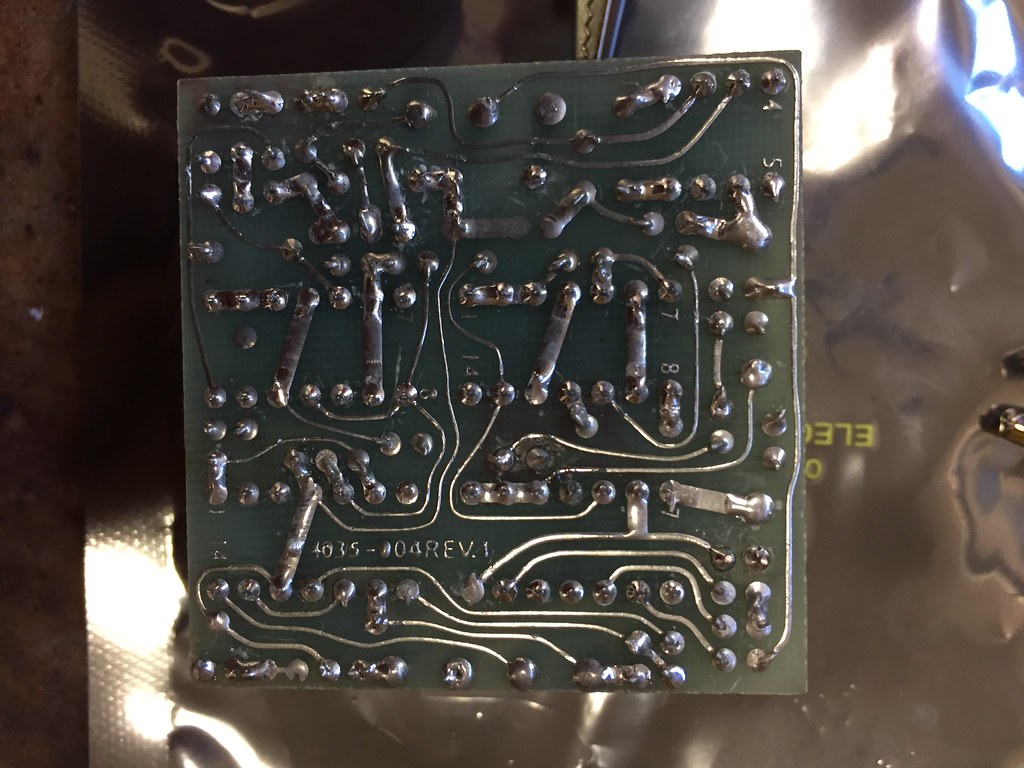
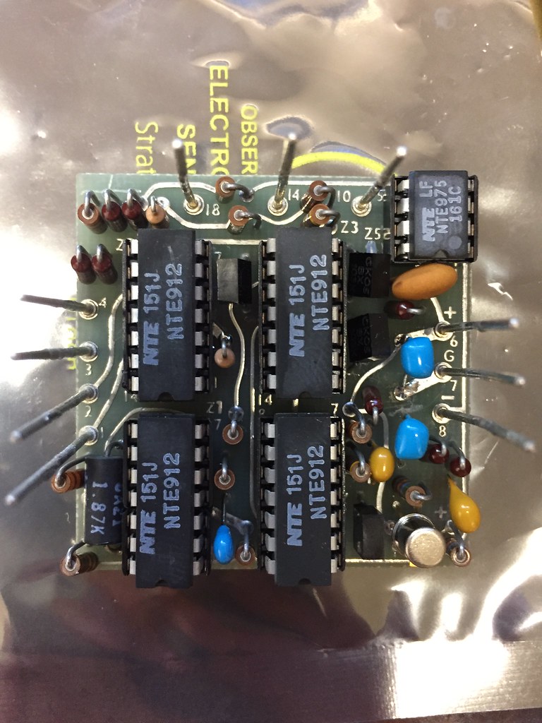
I'm wondering if there's any testing I can do to help narrow the problem down? I was probing with the multimeter on Z3 and Z4 and see rather large DC voltages from 5 to 7.5 V on most of the pins. This seems wrong to me, but I am no electronics guru. Anyway, I'll put some pictures below so ya'll can see if there's anything obviously hosed on this thing. ANY help would be massively appreciated. I'm beating my head against a wall here lol!

 |
|
|
Back to top
|
|
 |
gabbagabi

Joined: Nov 29, 2008
Posts: 652
Location: Berlin by n8
Audio files: 23
|
 Posted: Thu Jul 19, 2018 12:18 am Post subject: Posted: Thu Jul 19, 2018 12:18 am Post subject:
|
  |
|
Hi,
and 
something:
Not everyone has the schematic of this in the storage.
it it always a good idea to post a link to the schematic,
the very best idea is add furter a screenshot of the corresponding section of the schemo and attach it.
meanwhile play the old game: measure on the ic pins if the Supply voltages are present and then see how long u can trace the signal.
Good luck! |
|
|
Back to top
|
|
 |
devinw

Joined: Jul 18, 2018
Posts: 17
Location: Portland, OR
|
|
|
Back to top
|
|
 |
mph

Joined: Aug 25, 2007
Posts: 87
Location: France
|
 Posted: Fri Jul 20, 2018 4:57 am Post subject: Posted: Fri Jul 20, 2018 4:57 am Post subject:
|
  |
|
Just an idea, did you check the switches and potentiometers in the audio mixer section?
A bad contact somewhere and the signal won't be routed properly, and bad contacts and dead pots are a common issue on the Ody.
You can follow the signal with your scope and see where it disappears.
You can also reflow the solders of the long pins, they could break at the base and it won't be visible. |
|
|
Back to top
|
|
 |
devinw

Joined: Jul 18, 2018
Posts: 17
Location: Portland, OR
|
 Posted: Fri Jul 20, 2018 8:13 am Post subject: Posted: Fri Jul 20, 2018 8:13 am Post subject:
|
  |
|
| mph, word.. audio mixer is working. I put a waveform up on VCO 1 or 2 on the mixer (or noise) and get it at pin 1 on the filter (audio input). Then the signal is present on pin 12 of Z2 (see schematic) as it should, then it goes away. If I read the schematic right, that same signal should be on pin 14 of Z2 as well? But, I just see a DC voltage.... I've checked the soldering on this chip 100 times and have swapped in several brand new 3086 chips too and same! Craziness! |
|
|
Back to top
|
|
 |
mph

Joined: Aug 25, 2007
Posts: 87
Location: France
|
 Posted: Sun Jul 22, 2018 7:10 am Post subject: Posted: Sun Jul 22, 2018 7:10 am Post subject:
|
  |
|
Hi
pin2 on the filter pcb (Z2 pin12 ) is used for the feedback path, you should get a signal here depending on the Resonance pot setting, but the signal comes from filter output at filter pcb pin10.
So if the signal does not pass the filter itself that's normal to not have a signal here.
If continuity test of the tracks around Z2 (and around the filter on the Ody pcb) is fine too, maybe the filter position is simply "off" due to a problem in the CV section (is the 1K87 tempco ok?).
What voltages do you read at TP1 on the Ody schematic when the VCF is set to KBD CV Tracking and you play some notes on the keyboard?
I was suggesting a test of the sliders, because if the Frequency slider is dead and set to a very high frequency, even with max resonance you may hear nothing at all (but you should see a very weak signal on the scope at filter pcb pin10 anyway). |
|
|
Back to top
|
|
 |
devinw

Joined: Jul 18, 2018
Posts: 17
Location: Portland, OR
|
 Posted: Mon Jul 23, 2018 8:32 am Post subject: Posted: Mon Jul 23, 2018 8:32 am Post subject:
|
  |
|
| mph wrote: | Hi
pin2 on the filter pcb (Z2 pin12 ) is used for the feedback path, you should get a signal here depending on the Resonance pot setting, but the signal comes from filter output at filter pcb pin10.
So if the signal does not pass the filter itself that's normal to not have a signal here.
If continuity test of the tracks around Z2 (and around the filter on the Ody pcb) is fine too, maybe the filter position is simply "off" due to a problem in the CV section (is the 1K87 tempco ok?).
What voltages do you read at TP1 on the Ody schematic when the VCF is set to KBD CV Tracking and you play some notes on the keyboard?
I was suggesting a test of the sliders, because if the Frequency slider is dead and set to a very high frequency, even with max resonance you may hear nothing at all (but you should see a very weak signal on the scope at filter pcb pin10 anyway). |
Yeah 1.87k Tempco is OK, I had it off when installing one of the 4 DIP sockets and checked it.
I'll check TP1, but pretty sure Freq slider is OK because I can see a decreasing voltage on the control pin of the filter as I slide it up and down. Also, this synth has all new SynthChaser sliders on it and the frequency slide was definitely working proper before the filter went kaput.
One thing I need to do today is pick up a 3.3pf cap that stabilizes the LM301 Op amp (C5 on the schematic). I took it off because it's the last cap that hasn't been replaced on this guy and looks sort of chipped. But it's a ceramic, which I've never seen fail, but whatever. I'll snag one at the electronics store today on my lunch and pop it in tonight and see if anything changes. |
|
|
Back to top
|
|
 |
gabbagabi

Joined: Nov 29, 2008
Posts: 652
Location: Berlin by n8
Audio files: 23
|
 Posted: Mon Jul 23, 2018 9:03 am Post subject: Posted: Mon Jul 23, 2018 9:03 am Post subject:
|
  |
|
as i see it second time in a short while:
if you wanna do it right, spell "kaputt" with double-T  |
|
|
Back to top
|
|
 |
devinw

Joined: Jul 18, 2018
Posts: 17
Location: Portland, OR
|
 Posted: Mon Jul 23, 2018 9:06 am Post subject: Posted: Mon Jul 23, 2018 9:06 am Post subject:
|
  |
|
| g.gabba wrote: | as i see it second time in a short while:
if you wanna do it right, spell "kaputt" with double-T  |
I dunno man:
https://www.merriam-webster.com/dictionary/kaput
"variants: or less commonly kaputt "  |
|
|
Back to top
|
|
 |
gabbagabi

Joined: Nov 29, 2008
Posts: 652
Location: Berlin by n8
Audio files: 23
|
 Posted: Mon Jul 23, 2018 9:24 am Post subject: Posted: Mon Jul 23, 2018 9:24 am Post subject:
|
  |
|
hm,
it is, at least i thought, a german word.
As i hear the whole day BBC radio, and never heard it there, i would say it is at least uncommon in english.
May it comes from Philadelphia Dutch?
Anyway, i love those language interconnections.
edit: of course it is written there: "German speakers adopted "capot," but respelled it "kaputt"  |
|
|
Back to top
|
|
 |
devinw

Joined: Jul 18, 2018
Posts: 17
Location: Portland, OR
|
 Posted: Mon Jul 23, 2018 9:41 am Post subject: Posted: Mon Jul 23, 2018 9:41 am Post subject:
|
  |
|
| g.gabba wrote: | hm,
it is, at least i thought, a german word.
As i hear the whole day BBC radio, and never heard it there, i would say it is at least uncommon in english.
May it comes from Philadelphia Dutch?
Anyway, i love those language interconnections.
edit: of course it is written there: "German speakers adopted "capot," but respelled it "kaputt"  |
Yes, German origin I think for sure....with 2 Ts. It is pretty common in English though, especially amongst East Coast people, New Yorker's, Jewish influence. |
|
|
Back to top
|
|
 |
devinw

Joined: Jul 18, 2018
Posts: 17
Location: Portland, OR
|
 Posted: Mon Jul 30, 2018 9:16 am Post subject: Posted: Mon Jul 30, 2018 9:16 am Post subject:
|
  |
|
Welp, for those interesteed I fixed it. I feel like bonehead, but I had replaced 2 trimmer pots that were bad (the VCA CVR and the VFC Balance). It turns out I accidentally put a 10k trimmer on the VCF balance, but it should be a 1k! Really silly. I bypassed the trimmer in my diagnosing and patched in a 1k and POOF it works. Doh!
So now I have unncessarily rebuilt almost every component on this 4035, lol.
Now I also have a CES Sound replica 4035 module that I had purchased in case I couldn't fix my original, so it will be for sale. $100 and it's yours. $130 new and it's untouched. |
|
|
Back to top
|
|
 |
gabbagabi

Joined: Nov 29, 2008
Posts: 652
Location: Berlin by n8
Audio files: 23
|
 Posted: Tue Jul 31, 2018 8:56 am Post subject: Posted: Tue Jul 31, 2018 8:56 am Post subject:
|
  |
|
| glad to hear that its working again |
|
|
Back to top
|
|
 |
|

