| Author |
Message |
colorbars
Joined: Oct 29, 2015
Posts: 8
Location: Canada
|
 Posted: Tue Jul 31, 2018 5:44 am Post subject:
Interfacing lunetta with other modular Posted: Tue Jul 31, 2018 5:44 am Post subject:
Interfacing lunetta with other modular |
  |
|
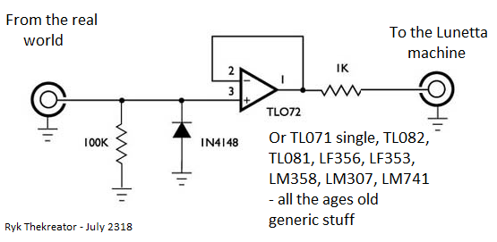
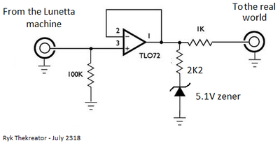
Recently shared with me from a long time lunetta mad scientist and forum member for protecting lunetta from eurorack etc and also protecting eurorack etc from lunetta! I’ve attached their diagrams for input and output protection, please comment if you have any recommendations or Improvements!
| Description: |
|
| Filesize: |
31.48 KB |
| Viewed: |
6241 Time(s) |
|
| Description: |
|
| Filesize: |
31.38 KB |
| Viewed: |
6241 Time(s) |
|
|
|
|
Back to top
|
|
 |
PHOBoS

Joined: Jan 14, 2010
Posts: 5603
Location: Moon Base
Audio files: 705
|
| Posted: Tue Jul 31, 2018 10:21 am Post subject:
|
|
|
ok, my thoughts on it, let's see
For the first circuit there shoud be a resistor in series with the input. Without this the diode will just short negative voltages to ground
which can be bad for modules (depending on the kind of protection they have) and it will also affect the signal if you would use it with
a passive multiple.
For connecting to digital inputs I'd use a comparator instead of a voltage follower. I actually did make a circuit for that recently:

(note: the AND gate is made by just having a switch in series).
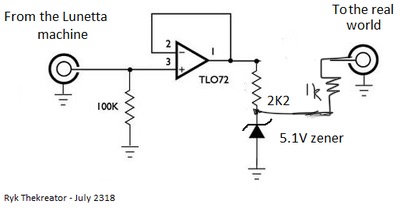
For the second circuit the output should be taken from the connection between the zenerdiode and the 2K2 resistor, otherwise the zener
doesn't have much effect besides wasting current.
_________________
"My perf, it's full of holes!"
http://phobos.000space.com/
SoundCloud BandCamp MixCloud Stickney Synthyards Captain Collider Twitch YouTube
Last edited by PHOBoS on Tue Jul 31, 2018 1:06 pm; edited 1 time in total |
|
|
Back to top
|
|
|
colorbars
Joined: Oct 29, 2015
Posts: 8
Location: Canada
|
| Posted: Tue Jul 31, 2018 12:10 pm Post subject:
|
|
|
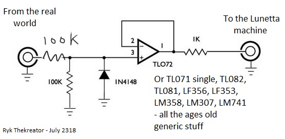
Like so, Phobos?
| Description: |
|
| Filesize: |
35.05 KB |
| Viewed: |
6153 Time(s) |
|
| Description: |
|
| Filesize: |
16.98 KB |
| Viewed: |
6153 Time(s) |
|
|
|
|
Back to top
|
|
|
Richarius
Joined: Feb 22, 2014
Posts: 81
Location: Kitchener, Ontario, Canada
Audio files: 1
|
| Posted: Tue Jul 31, 2018 12:28 pm Post subject:
|
|
|
PHOBoS! Omg, omg. I thought I knew the littlest bits of theory over the years of DIY electronics but ...  
The above error corrections of yours, were as to my schematics that Colorbars had shared.
I remembered that the 2k2-2k7 as per the zener, is for current limiting as to the load that it drops. I had forgotten though, having to take the output from between the resistor and the zener. Thank you for THAT reminder!
The other one ... with the diode to Ground to protect from -V "coming in" I hadn't even considered the amount of current that COULD be transferred that way.
I believe now, that I had mistakenly assumed, the 100k to Ground impedence for the chip, from the LOGIC world, had applied equally, to the opamp world! Hence ... my often putting them to Ground, instead of in Serial.
I know that with Logic, with have to tie them either HIGH or to Ground and using the 100k gives that impedance. (All together, rather than floating the input.)
I'd posted that pair at my private Lunetta forum, for reference as ... that is exactly what I'll be doing within days - the 'interfacing' between my Euro rack and my Lunetta rack. Having had interfacing problems in the past ...
Here now - the comparator schfematic that you had posted earlier, works perfectly to take care of the +5V points from Euro, that wont do anything in a +12V Lunetta machine.
And the "AND" portion, you'd partially clarified but ... I still can't 'see' the AND function possibility, in the circuit? Sorry ... is it ... my age? Hahahaha.
Thank you for possibly correcting my errors! I never mind being shown, when I'm wrong with something!
Still learning and always will be.
Off to prototype yet more new ideas, from earlier today. 
_________________
https://tsol.space/crafting/composing-music/albums/ - my punk, ambient and experimental tunes |
|
|
Back to top
|
|
|
PHOBoS
Joined: Jan 14, 2010
Posts: 5603
Location: Moon Base
Audio files: 705
|
| Posted: Tue Jul 31, 2018 1:25 pm Post subject:
|
|
|
| colorbars wrote: | | Like so, Phobos? |
almost, but place the resistor on the input between the 100K resistor to GND and the diode, otherwise it will
form a voltage divider. Oh and I'd use 1K, although 100K will probably work fine too.
| Richarius wrote: | | And the "AND" portion, you'd partially clarified but ... I still can't 'see' the AND function possibility, in the circuit? Sorry ... is it ... my age? Hahahaha. |
It's an AND function in the sense that it 'AND's the input signal with the state of the switch. Originally the switch was connected to V+ and I
created a more proper AND function using the comparators in a different configuration. But I realized I could get the same result with placing
the switches in series with the input signals. 
you can still see it in the way I designed the panel art:

_________________
"My perf, it's full of holes!"
http://phobos.000space.com/
SoundCloud BandCamp MixCloud Stickney Synthyards Captain Collider Twitch YouTube |
|
|
Back to top
|
|
|
PHOBoS
Joined: Jan 14, 2010
Posts: 5603
Location: Moon Base
Audio files: 705
|
| Posted: Tue Jul 31, 2018 1:45 pm Post subject:
|
|
|
oh and another thing. You could place the zenerdiode on the input of the opamp instead of the output. (So the circuit would
be exactly the same as the other one but with a zenerdiode instead) This way you don't get any extra current limiting from
the 2K2 resistor so you can drive a bit more with it. Downside is that it will 'pull more current' from what you connect to the input.
_________________
"My perf, it's full of holes!"
http://phobos.000space.com/
SoundCloud BandCamp MixCloud Stickney Synthyards Captain Collider Twitch YouTube |
|
|
Back to top
|
|
|
|

 Forum index » DIY Hardware and Software » Lunettas - circuits inspired by Stanley Lunetta
