| Author |
Message |
Ricko
Joined: Dec 25, 2007
Posts: 251
Location: Sydney, Australia
Audio files: 27
|
 Posted: Thu Jul 11, 2019 2:17 am Post subject:
A new envelope follower Posted: Thu Jul 11, 2019 2:17 am Post subject:
A new envelope follower |
  |
|
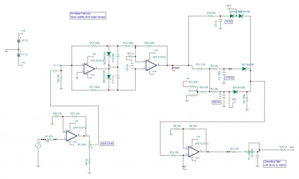
Here is a schematic for a new Envelope Follower.
I think it has two ideas that I have not seen before. (In fact, either by themselves are functional, and I am not sure that combining them does much.)
The circuit is level adjuster, then a precision fullwave rectifier, then a filter/diode mixer, then a output smoother.
The fullwave rectifier is unusual because it has some unexpected capacittors. The C10 and C11 play with the waves so there is less "gap", and the big C9 filter causes a bit of a boost/kick to emphasize upswings to compensate for the smoother.
The filter/diodes circuit previously had a lot more sections. Basically, on an upgoing signal the fastest (highest frequency) will win, while on an outgoing wave the slowest will win. The diode drops (with r7 and r1) acts as a noise threshold.
| Description: |
|
| Filesize: |
104.88 KB |
| Viewed: |
1554 Time(s) |
| This image has been reduced to fit the page. Click on it to enlarge. |
|
| Description: |
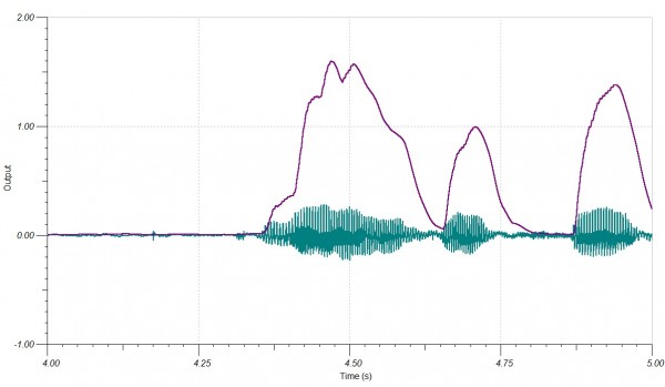
| Simulation. This is some speech. you can see the front is eager. Smoothing is set to maximum, so there is some smear/delay. |
|
| Filesize: |
82.2 KB |
| Viewed: |
367 Time(s) |
| This image has been reduced to fit the page. Click on it to enlarge. |
|
Last edited by Ricko on Wed Sep 11, 2019 6:13 am; edited 1 time in total |
|
|
Back to top
|
|
 |
EATyourGuitar
Joined: Oct 28, 2010
Posts: 59
Location: Providence, RI
|
| Posted: Mon Sep 09, 2019 6:32 pm Post subject:
|
|
|
if you the input is AC coupled, which it is here, you can use a half wave rectifier to reduce parts count and therefor cost, size, build time etc.. there are many ways to do the low pass filtering. the simplest way is RC filter. you can also use an op amp integrator. some people might want fast rise time and slow release. this can be done with diodes and resistors or pots somewhere near the cap. the concept is the same no matter what kind of filter. there will always be a cap. it will charge and discharge through different paths when diodes are involved.
the scope shot looks good so I think it is a success. you can challenge yourself to make it simpler without losing performance. |
|
|
Back to top
|
|
|
Grumble

Joined: Nov 23, 2015
Posts: 1294
Location: Netherlands
Audio files: 30
|
| Posted: Mon Sep 09, 2019 11:33 pm Post subject:
|
|
|
| EATyourGuitar wrote: | | you can use a half wave rectifier to reduce parts count and therefor cost, size, build time etc. |
Maybe you can reduce the number of used parts, but the ripple will increase by using half-wave rectification so not a very good idea.
_________________
my synth |
|
|
Back to top
|
|
|
Ricko
Joined: Dec 25, 2007
Posts: 251
Location: Sydney, Australia
Audio files: 27
|
| Posted: Wed Sep 11, 2019 6:12 am Post subject:
|
|
|
Yes, E Guitar is bang on the money that allowing adjustment of timing is super important for envelope followers.
For simplification, it would be to either have the lagged/shifted full wave circuit, or the lagged diode mixing section, rather than both. A halfwave rectifier couldnt use the capacitor effects here, so it would be a different circuit.
Some say that the disadvantage of half wave rectifier in envelope follower applications is that it adds a slight delay or randomness to the start of notes, depending on whether your input starts on the positive or negative part of its cycle: an effect supposedly noticeable on the lowest bass notes, especially if you use a simple rc filter without the kick circuit or diode mixer. |
|
|
Back to top
|
|
|
cyclic

Joined: Mar 15, 2015
Posts: 95
Location: hobart
|
| Posted: Sun Sep 15, 2019 8:05 pm Post subject:
|
|
|
Hey,
Im very interested in this as im working on env following right now too.if i get something im happy with ill be laying out a pcb, either single side for home or double for professional fabbing, in which case I'd totally do a run and share them at cost.
I use bike dynamos as ac and dv voltage sources, they work from about 0.1hz to 300hz and i want to follow envelopes above about 20hz. Below that we can just manipulate the generators directly for cv.
I tried the mfos follower but it had a full 1v ripple which is way too much for me.
I currently was looking at the mutable instruments Ears and have cut it back, currently have about 0.1v ripple but has some other issues for my setup i havent sorted yet.
Im aiming for a 0-5v cv from 10vp2p inputs on +_12v power.
Have you done any work on the simpler schematic you can share? Im not really an engineer so cant do the new electronics design, just the copy and mash up techniques!
Cheers |
|
|
Back to top
|
|
|
EATyourGuitar
Joined: Oct 28, 2010
Posts: 59
Location: Providence, RI
|
| Posted: Sat Sep 21, 2019 3:22 pm Post subject:
|
|
|
| as a kind of do both ways thing you could just put a full wave precision rectifier before an envelope follower built for half wave rectified audio. you can even use the same circuit OP posted. one of them gets tied to ground starting with the first differential signal after the rectifier. |
|
|
Back to top
|
|
|
cyclic
Joined: Mar 15, 2015
Posts: 95
Location: hobart
|
| Posted: Thu Sep 26, 2019 5:52 am Post subject:
|
|
|
Okay,
So ill admit that I havent built your circuit up yet but ive mucked about with the ears EF i have on my breadboard. The extra caps on the rectifier actually make the ripplenworse on that circuit.
Ill happily admit that i am after an EF for low frequencies which is much more challenging. At audio rate the Ears EF, even my cut back one works quite well. Its got more parts than i understand, and when im back from a month away ill cut it back to see what the simplest workable design is.
But ive had another idea entirely, which I think fits well with the OP topic of a new EF and in my conceptualisation gives a no ripple low frequency capable EF:
First a precision rectifier. (1 opamp}
Then ken stones slope detector to pick when the wave falls from peak (1 opamp maybe if i ditch the other segments)
Convert square to trigger.
Trigger to a sample and hold IC.
Rectified signal also to IC.
In my idea this gives a square EF which will be a bit steppy but not ripply, so its just a question of which is better. For full square haters a fast slew could be installed to smooth it off.
Actually, I think maybe you could actually skip the rectifier wirhout much loss of detail.
Only issue I can foresee is at end of envelope im not sure how to trigger it back down to 0v, and it will hold at whatever the last trigger sends.
I have tested the slope detector and it seems totally fine as a timing trigger generator for this idea from 0.1hz to 20khz.
2 opamps, (3 if slewed and buffered?) 1 SH chip.
What do you think? |
|
|
Back to top
|
|
|
EATyourGuitar
Joined: Oct 28, 2010
Posts: 59
Location: Providence, RI
|
| Posted: Thu Sep 26, 2019 7:27 am Post subject:
|
|
|
| Your idea of a hold circuit won't work. What triggers hold? What triggers the release of the hold? How will you filter all the harmonics created by the staircase? With another envelope follower? It is easy to detect when amplitude is increasing but it is much harder to detect when amplitude is decreasing since periodic waveform will always return to 0v every period or every half period. This is why it requires time functions such as a low pass filter. |
|
|
Back to top
|
|
|
cyclic
Joined: Mar 15, 2015
Posts: 95
Location: hobart
|
| Posted: Thu Sep 26, 2019 2:03 pm Post subject:
|
|
|
Ok,
Maybe i wasnt obvious enough.
The triggers come from the slope detector which creates a square wave on any downgoing portion only.
This square is then conditioned to a.narrow pulse to trigger an LF398.
This trigger will occur just after the peak of each waveform and bench testing showed it is fine well into proper audio, which it totally should since its just an opamp comparator.
I am particularly interested in reducing ripple all the down to a low frequency into subaudio without making it so slow as to be unusable.
There is no need to trigger release on the LF398 until the end of envelope which is what I had asked about ideas for.
I dont get the harmonics problem at all! How is making a staircase EF going to create anything relevant except the actual envelope if I dont filter it?
Unfortunately I wont get a chance to test for a month,
Cheers |
|
|
Back to top
|
|
|
blue hell
Site Admin

Joined: Apr 03, 2004
Posts: 24084
Location: The Netherlands, Enschede
Audio files: 278
G2 patch files: 320
|
| Posted: Thu Sep 26, 2019 3:03 pm Post subject:
|
|
|
| cyclic wrote: | | Unfortunately I wont get a chance to test for a month |
Some ideas then maybe to look into during that month .. you might end up with a processor to do it "well" or "best", this is not an easy thing to do:
https://www.kvraudio.com/forum/topic-497451.html
https://www.dsprelated.com/showarticle/938.php
and also .. the subject of analytical signals has something to say about envelope detection:
https://en.wikipedia.org/wiki/Analytic_signal#Envelope_and_instantaneous_phase
Anyways, some ideas for doing it digitally.
The hilbert filter you might see being used in some of the ideas can (also) be done in analog electronics .. but it uses a lot of components .. when I'm not mistaken there is a Jürgen Haible design for a dome filter, which would have to be scaled down in frequency probably.
_________________
Jan
also .. could someone please turn down the thermostat a bit.
 |
|
|
Back to top
|
|
|
Grumble
Joined: Nov 23, 2015
Posts: 1294
Location: Netherlands
Audio files: 30
|
|
|
Back to top
|
|
|
cyclic
Joined: Mar 15, 2015
Posts: 95
Location: hobart
|
| Posted: Tue Oct 01, 2019 5:21 pm Post subject:
|
|
|
Thanks guys, quite a lot of reading there and I see that what I was trying to describe is a peak hold circuit. And the problems and solutions described are almost the ones I was considering so its also nice to know I am learning this stuff.
The analog devices article is certainly worth a go for me. More ICs than desired but if it works im ok with that as its still looking like a very doable solution for me. |
|
|
Back to top
|
|
|
cyclic
Joined: Mar 15, 2015
Posts: 95
Location: hobart
|
| Posted: Fri Nov 01, 2019 9:38 pm Post subject:
|
|
|
I have built this circuit and it does indeed have a fast response and a low ripple, and for some circumstances it would be very useful, but it comes at a cost of significantly increased complexity, and the need to tune the sampling clock to the frequency of the audio sample. for some situations this would be fine, but I'm not so sure about being super for my use.
I am trying to capture very low frequencies to the low audio threshold and at that rate we certainyl see some significant stepping. I also got some bleed through of the clock - although that is potentially a breadboard issue, plus the fact that I, um, didn' put any power decoupling caps on the breadboard...
I would say its main advantage is very fast decays matching the audio way better than a capacitor can manage without significant ripple, so in that sense I certainly agree that it is a faster and lower ripple EF.
I took some scope shots, but obviously I can't show the input and both out puts at once so you'll have to do a bit of to and fro-ing and
probably I will now actually build the top schematic and compare them all!
| Description: |
|

Download |
| Filename: |
bb1_____.bmp |
| Filesize: |
146.3 KB |
| Downloaded: |
220 Time(s) |
| Description: |
|
Download |
| Filename: |
bb2_____.bmp |
| Filesize: |
146.3 KB |
| Downloaded: |
234 Time(s) |
| Description: |
|
Download |
| Filename: |
bb3_____.bmp |
| Filesize: |
146.3 KB |
| Downloaded: |
214 Time(s) |
| Description: |
|
Download |
| Filename: |
NewFile2.bmp |
| Filesize: |
146.3 KB |
| Downloaded: |
209 Time(s) |
| Description: |
|
Download |
| Filename: |
NewFile1.bmp |
| Filesize: |
146.3 KB |
| Downloaded: |
221 Time(s) |
|
|
|
Back to top
|
|
|
EATyourGuitar
Joined: Oct 28, 2010
Posts: 59
Location: Providence, RI
|
| Posted: Mon Jan 20, 2020 9:01 am Post subject:
|
|
|
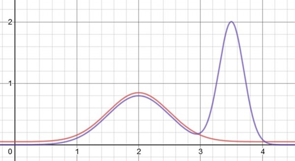
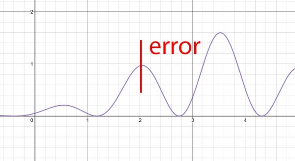
building a circuit or writing software to detect the loudest part of an incomplete data set while it is in transmission has always been a game of probability and never scientific certainty. in digital systems you could say that the loudest part is binary 1111111111111111. but your chances of getting that at the DAC without clipping is close to 1/inf. (actually probably more like (1/(2^16))/(2^17)).
I made a picture to show that the data that has been processed could potentially be useless in preventing all false positives for largest peak detection. what comes down the wire after you detected a peak could be a real retraction or it could be the real peak you were looking for. there is no %100 perfect solution to this math problem. this is why all envelope followers that include a gate output have an adjustable threshold. you are really bullshitting yourself if you think you have a way to predict the future without already doing look ahead of the entire audio file that you want to extract peaks from.
what you will probably do, since I already see how you think, is build a circuit that will work best at one program level with one kind of music consistently hitting some average of peaks per second based on your calibration. this is not what you claim to be building. a machine that can always detect the loudest part of an incomplete signal by measuring an arbitrary amount of retraction over an arbitrary amount of time without knowing the program level or peak level. bottom line, your envelope follower will require audio to be loud enough to match your calibration. this is not a universal machine. it is a primitive rule based machine. the suggested designs are complicated filter networks that pretty much self calibrate like an automatic gain controller. not a perfect system but better than building a machine that labels all retractions as peaks.
| Description: |
|
| Filesize: |
51.05 KB |
| Viewed: |
125 Time(s) |
| This image has been reduced to fit the page. Click on it to enlarge. |
|
| Description: |
|
| Filesize: |
56.33 KB |
| Viewed: |
119 Time(s) |
| This image has been reduced to fit the page. Click on it to enlarge. |
|
|
|
|
Back to top
|
|
|
|

 Forum index » DIY Hardware and Software
