| Front Page | Radio | Media | Forum | Wiki | Links |

and electronic music
|
|
Dedicated to
experimental electro-acoustic and electronic music |
|
|
|
 Forum index » DIY Hardware and Software » Les Hall's Projects including eChucK Forum index » DIY Hardware and Software » Les Hall's Projects including eChucK |
|
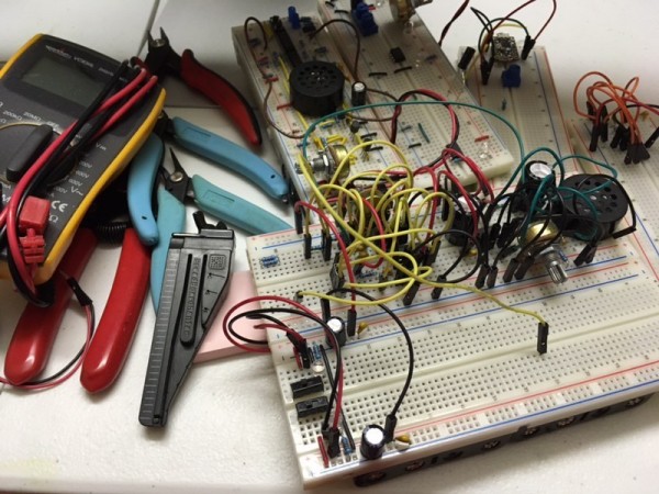
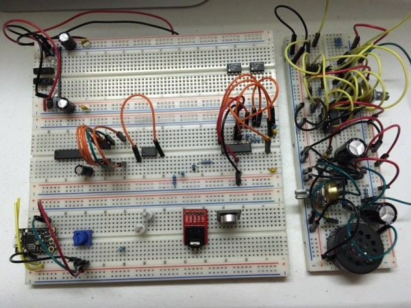
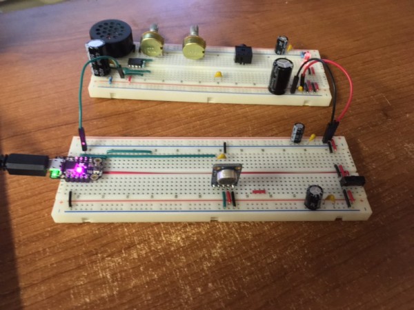
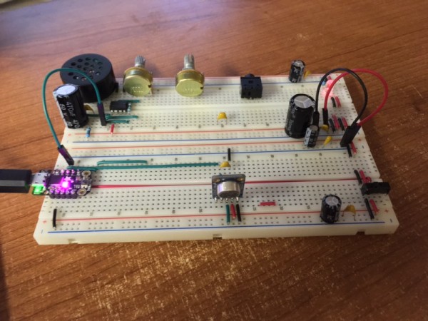
Breadboard Prototyping
|
 
|
Moderators: Inventor
Page 1 of 1 [4 Posts] |
View unread posts View new posts in the last week Mark the topic unread :: View previous topic :: View next topic |
| Author | Message | ||||||||||||||||||||||||||||||||
|---|---|---|---|---|---|---|---|---|---|---|---|---|---|---|---|---|---|---|---|---|---|---|---|---|---|---|---|---|---|---|---|---|---|
|
Inventor
Stream Operator  Joined: Oct 13, 2007 Posts: 6221 Location: near Austin, Tx, USA Audio files: 267 |
|
||||||||||||||||||||||||||||||||
|
|
|||||||||||||||||||||||||||||||||
|
Inventor
Stream Operator Joined: Oct 13, 2007 Posts: 6221 Location: near Austin, Tx, USA Audio files: 267 |
|
||||||||||||||||||||||||||||||||
|
|
|||||||||||||||||||||||||||||||||
|
Inventor
Stream Operator Joined: Oct 13, 2007 Posts: 6221 Location: near Austin, Tx, USA Audio files: 267 |
|
||||||||||||||||||||||||||||||||
|
|
|||||||||||||||||||||||||||||||||
|
Inventor
Stream Operator Joined: Oct 13, 2007 Posts: 6221 Location: near Austin, Tx, USA Audio files: 267 |
|
||||||||||||||||||||||||||||||||
|
|
|||||||||||||||||||||||||||||||||
|
|
Moderators: Inventor
Page 1 of 1 [4 Posts] |
View unread posts View new posts in the last week Mark the topic unread :: View previous topic :: View next topic |
|
Forum index » DIY Hardware and Software » Les Hall's Projects including eChucK |
|
You cannot post new topics in this forum You cannot reply to topics in this forum You cannot edit your posts in this forum You cannot delete your posts in this forum You cannot vote in polls in this forum You cannot attach files in this forum You can download files in this forum |