ixtern
Joined: Jun 25, 2018
Posts: 145
Location: Poland
|
 Posted: Mon Oct 14, 2019 1:44 am Post subject:
fonitronik Thomas Henry x4046 VCO mods Posted: Mon Oct 14, 2019 1:44 am Post subject:
fonitronik Thomas Henry x4046 VCO mods |
  |
|
After building fonitronik's version of Thomas Henry x4046 VCO I felt lack of some features. In general I don't like coarse frequency pots in VCO as they are a big source of instability and wide range of control is usually too wide for me.
I know that x4046 VCO in not a top quality VCO but for me every VCO used to play tempered scale paralell with some other VCOs should have stable reference voltages for the pitch controls.
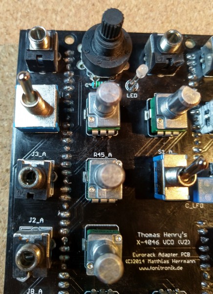
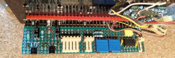
fonitronik's PCB for TH x4046 VCO is very mod-unfriendly - dense layout, very dark soldermask (obscuring tracks) and full ground plane on both side with heavy thermal capacity (resulting in ground points soldering problems)
So making mods for this PCB is not an easy and elegant work.
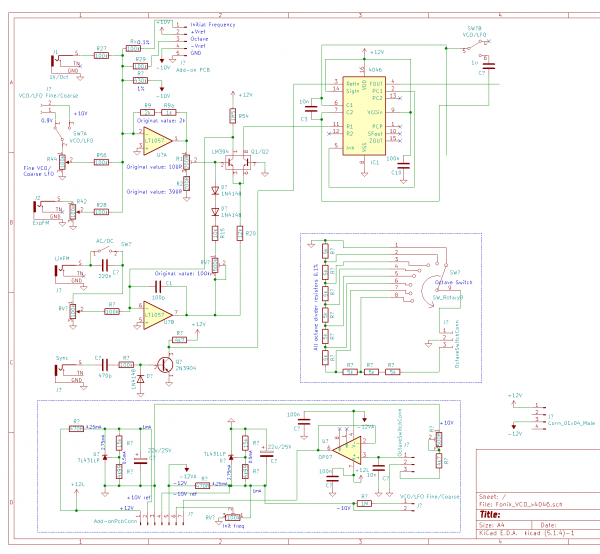
I have made following mods:
1. +-10V reference voltages (TL431 based).
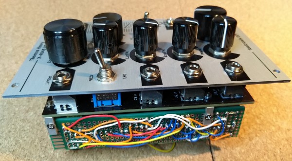
2. Octave switch instead of coarse frequency pot
3. Trimpot for setting exact initial frequency plus additional resistor to set the coarse range.
4. Fine frequency pot now is dual-functionality: in VCO mode it is fine (few semitones) control, in LFO mode it is coarse (up to 10 octaves) control.
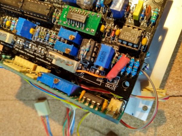
Most of the parts were located on the separate board, only two resistors for pitch control were mounted on the original VCO PCB and octave switch with resistors on the panel PCB. Some track were needed to be cut (+-12V to the coarse/fine pots, tracks from the LED to the VCO/LFO switch).
Octave switch was chosen simple and small to fit in the place of original coarse pot, if better but longer (depth) switch is to be used, pcb needs to be cut off. Please notice that 0.1% resistors were used for the octave voltage divider. Also trimpot was added to set exact +9.000 V for the divider.
430 kOhm resistor for initial frequency range was soldered on the backside of VCO PCB.
Due to fully occupied VCO/LFO switch there was no possible to connect LED the way it was. And I didn't wanted to connect LED directly to VCO triangle output (as it was, but for LFO only). For now LED is disconnected.
Here is the partial schematic with the changes:
| Description: |
|
| Filesize: |
72.5 KB |
| Viewed: |
401 Time(s) |
| This image has been reduced to fit the page. Click on it to enlarge. |
|
| Description: |
|
| Filesize: |
975.8 KB |
| Viewed: |
322 Time(s) |
| This image has been reduced to fit the page. Click on it to enlarge. |
|
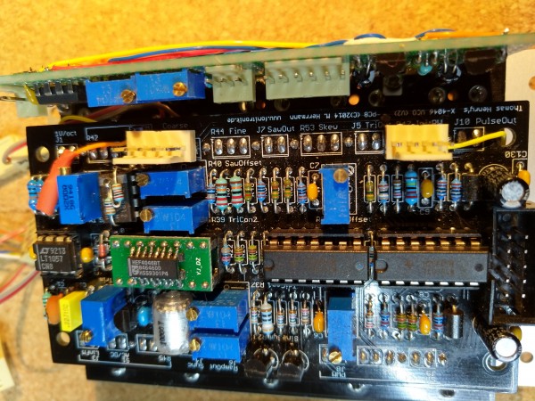
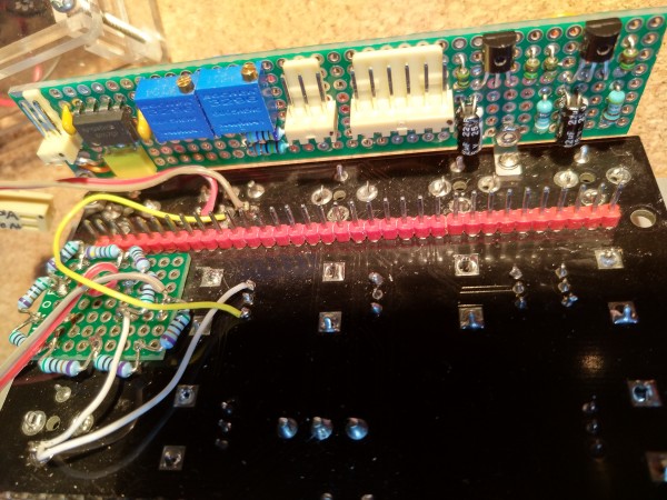
| Description: |
| Add-on PCB and octave voltage divider PCB. |
|
| Filesize: |
2.94 MB |
| Viewed: |
317 Time(s) |
| This image has been reduced to fit the page. Click on it to enlarge. |
|
Last edited by ixtern on Mon Oct 14, 2019 8:23 am; edited 5 times in total |
|

 Forum index » DIY Hardware and Software » fonik's place