| Author |
Message |
Silesius

Joined: Feb 12, 2010
Posts: 65
Location: Berlin
|
 Posted: Sun Jun 06, 2010 2:17 pm Post subject:
How to connect Lunetta modules Posted: Sun Jun 06, 2010 2:17 pm Post subject:
How to connect Lunetta modules
Subject description: Beginner making his first Lunetta |
  |
|
Hi everybody,
I'm building my first Lunetta project with information found on this awesome forum; so far I have 4 clocks from a 40106, a module with 4 Nand gates, and a small mixer. I'm planning on make a small modular. For the moment I put the modules in small boxes, and I plan on making a nice wooden box with an aluminum front panel. But that will be in several months, because I'm really new in electronics (I'm a philosophy teacher!  ) and I need to learn a lot. ) and I need to learn a lot.
As you can imagine, I'm having lots of problems I'm not able to solve; but searching here and there I always find something new to try.
I would like to know how to make the connections between different modules in a way they don't interact in unwanted manners.
For example, I've heard here somewhere that you can use a 100K resistor to ground tied to every input. Is that a good idea? And what about the outputs? What do you use in your setups? Would diodes a good idea (sorry but I just have a very slight idea about what a diode do  ) )
Also, one of my biggest problems is that I don't know how to power the modules. I wanted to use 9v batteries. My 40106 clocks work ok, but when I try to connect them with my 4093 nand gates (with the same battery) they cause a lot of interferences and strange things. So I use two batteries. And now everything is fine. But my question is: do I have to use a different battery for every chip I use? And, on the other side: If I find a solution for this (with your help, I hope), it's possible to power 10 modules or so with just one 9v battery? I'll keep asking newbie questions for a while, I hope you'll be indulgent with me (and my terrible english). I saw someone talking about a making a beginners thread. I think it would be a great idea. I will wait a little and, if not, i will start myself (some kind of Lunetta for very very dummies).
Thanks for your help. |
|
|
Back to top
|
|
 |
Sam_Zen

Joined: Mar 08, 2008
Posts: 251
Location: NL
|
| Posted: Sun Jun 06, 2010 5:25 pm Post subject:
|
|
|
A battery has a positive and a negative voltage.
You can use several ICs with one battery, as long as you make sure to connect each chip to the common negative voltage (V-, ground)
_________________
0.618033988 |
|
|
Back to top
|
|
|
Rykhaard
Joined: Sep 02, 2007
Posts: 1290
Location: Canada
|
| Posted: Sun Jun 06, 2010 8:35 pm Post subject:
|
|
|
Welcome to electro-music Silesius.  (Wonderful sounding Latin'ish name. ) (Wonderful sounding Latin'ish name. )
There are many very helpful people here at EM, that helps make things easier for beginners, to begin. 
Now, to answer a few questions for you, as I'd been there myself in the mid 80's as well.
In no particular order ...
A Legend of sorts, previous to the explanations:
As I've had explained to me in the past, you may think of what's coming out of a battery (or out from the outlet in a house) to power things, as 'water'.
- The SPEED that the 'water' is travelling, is the same as the VOLTS that the source is putting out.
- The AMOUNT of the 'water' that is coming out from the source at that 'speed', is AMPS (or current)
- if you multiply the amount of Volts by the amount of Amps, your answer will give you the amount of WATTS that the supply is.
(Any questions, just ask. In an opposite direction - with yourself being a Philosophy teacher and myself being a self-considered Philosopher for the last 12 years ... I could probably come up with MANY questions in that direction.  ) )
Now - on to your questions:
A Diode - in most cases, only allows CURRENT, to travel in 1 direction. (Under normal operation.)
A Resistor - will limit just how MUCH current, is able to travel through that resistor.
A Capacitor - may be thought of as a 'water bucket'. The capacitor when it has a current coming into it, will take in current until the measurable voltage from that capacitor to Ground, is equal to the voltage of that current coming in and filling that capacitor.
Also - a capacitor will BLOCK a DC voltage (Direct Current voltage) - the same current that the capacitor is charging up with. But, a capacitor will allow to pass through it, an AC voltage (Alternating Current voltage)
DC voltage comes from a battery.
AC voltage comes out from the outlet in your wall / walls / etc.
Now - you had mentioned building the 4 x CD40106 oscillators in 1 section, which were all working fine, by themselves.
You had also built 4 x NAND gates around the CD4093 in another section, which would cause PROBLEMS with the 4 x oscillators, when both chips were powered from a single battery! 
Here, we have 4 oscillators. Each of them are turning ON and OFF as each of their Capacitors are filling with current and then emptying themselves of the current. Each of those oscillators are causing draw of current from the battery. EACH of them. They will be causing a little bit of trouble for that poor little CD40106 as each of them oscillates.
As well - when the NAND gates in the CD4093 are switching ON and OFF, they ALSO will be drawing that current.
Each of those 2 chips will be taking away the current that is available FOR them from that single battery.
A solution here (that I wasn't taught until 1991), is add a SMALL capacitor as close as possible to the power INPUT pin, of EACH of those chips. That will help to give each of them a 'resevoir' of current, that they may draw from, when they wish to turn on and off, each of their oscillators.
The mostly standard value of capacitor for hooking up to the Positive Voltage input of each chip is:
0.1 microfarads (uF)
To assist a few chips that may be working together on a circuit board, is also a very good idea to have a larger capacitor, to act as a larger resevoir of current for 'everybody' that is on that circuit board. The greater the amount of chips that are on there, the larger the capacitor we normally use.
For just a few chips, a 10 microfarad capacitor is fine.
For a few more chips, a 47uF or 100uF capacitor will do the job.
Now - as to CMOS chip INPUTS. These little buggers can be fussy chips when they have Inputs that have NOTHING hooked up to them. It is best to always, hook up those inputs, - IF they are unused - to +V (positive voltage) or to Ground. This is dependant on what the function of each of those inputs IS.
When you are having inputs that DO have something hooked up to them, it is a standard practice in music electronics to give the inputs a 100,000 ohm impedance. 1 end of the 100k resistor (1/4 watt - is the standard size), can be hooked up directly to the input and the other end can be hooked up to the input connection to that chip's input.
Another way to do it, is to run the 100k resistor from the input pin to Ground and then the input connection for that chip's pin, to the junction of the 100k resistor and that chip's input pin.
(There are futher explanations relevant to that, but for the moment I'll just leave it at that - as I've been explaining a few things already and don't wish to dump too much down on you at 1 time. )
Finally - as to Outputs, it has been standard practice since about the mid 1970's, to put a 1,000 ohm 1/4 watt resistor on to the output pin from the chip. This is handy especially, if the Output is ever accidentally SHORTED to somewhere else, that output will only allow:
The Output Voltage DIVIDED by the Output Resistor's ohm rating amount of CURRENT, to short to where ever it is going.
Now that SHORT - will be pulling that MUCH current out of that chip! And that chip, without that protecting output resistor, may _NOT_ be very happy at all.
And now, REALLY, finally - that formula that I just dropped into your mental lap, is probably 1 of THEE most important formulas in electronics to memorize and become familiar with - Ohm's Law. To calculate it, we use the following specifications:
voltage = Volts as in a 9 volt batter = 9 volts
resistance = Ohms as in a 1,000 ohm (1k) resistor
current = Amps
Ohms law = :
VOLTS (V) divided by CURRENT (I) multiplied by OHMS (R)
or
VOLTS (V) = CURRENT (I) multiplied by OHMS (R)
CURRENT (I) = VOLTS (V) divided by OHMS (R)
OHMS (R) = VOLTS (V) divided by CURRENT (I)
Symbolically:
[/code]
And there we are for now, class. Aye. There is another new chap that has become interest in Lunetta building as well. Both of you could begin your own beginner's threads, or you could join in with his (which collectively, may be better for informational orgazination.) That's up to yourself and where you feel most comfortable.
More questions? Ask away! I remember what it were like to start, BEFORE the internet were public. Once I got onto it in 1991, the amount of help that I found were beyond any reasonable means of measuring! That, to me, were an absolute joy!
As to your language? I didn't find a single trouble in understanding a single word from you! It were perfect to me! 
Pax tecum, Silesius |
|
|
Back to top
|
|
|
Uncle Krunkus
Moderator

Joined: Jul 11, 2005
Posts: 4761
Location: Sydney, Australia
Audio files: 52
G2 patch files: 1
|
| Posted: Mon Jun 07, 2010 2:11 am Post subject:
|
|
|
I'd just like to point out that Rykhaard is obviously one of the most helpful people you will find, here or anywhere else! A gentleman and a scholar.
_________________
What makes a space ours, is what we put there, and what we do there. |
|
|
Back to top
|
|
|
tjookum

Joined: May 25, 2010
Posts: 360
Location: Netherlands
Audio files: 26
|
| Posted: Mon Jun 07, 2010 5:21 am Post subject:
|
|
|
once again rykhaard, great stuff! Ive checked out the deathlehem forum, some really nice info there too, good tip for beginners.
Hi silesius! Good to see another "newbie" getting into lunetta's. The learning curve might seem steep to begin with, but after you get your first bleeps going you will be addicted in no time.
_________________
There he goes. One of God's own prototypes. A high-powered mutant of some kind never even considered for mass production. Too weird to live, and too rare to die.
Hunter S. Thompson
movies
noise |
|
|
Back to top
|
|
|
adambee7
Joined: Apr 04, 2009
Posts: 420
Location: united kingdom
|
| Posted: Mon Jun 07, 2010 12:16 pm Post subject:
|
|
|
| He is a diamond. rykhaard also has his own forum for noise making with loads of really good schematics. |
|
|
Back to top
|
|
|
Rykhaard
Joined: Sep 02, 2007
Posts: 1290
Location: Canada
|
| Posted: Mon Jun 07, 2010 2:35 pm Post subject:
|
|
|
Slapping myself after pinching lots, trying to see if I'm really awake, reading all of this from Unkie Krunk; Tjookum and then Adambee7.
See guys? I TOL-YA that you shouldn't drink too MUCH of the 18 year old Macallan Single Malt Scotch that I sent y'all! Makes ya talk funny an' all that stuff!
Ahhh. Thank you greatly, the 3 of you! Appreciated, greatly. 
When I'm willing and capable, I just like helping others when I can, that's all. I don't know a heck of a lot of stuff and I have learned a TON of things from many wonderful people here, includcing Unkle Krunkus ... but when I'm able to babble something in assistance that I'm fairly comfy with, I'll give it a whack in hoping for success for those it's directed to. |
|
|
Back to top
|
|
|
Ajax
Joined: Apr 05, 2010
Posts: 63
Location: San Francisco
|
| Posted: Mon Jun 07, 2010 4:18 pm Post subject:
|
|
|
| That rant of brilliance should be in the Lunnetta guide Droffset is working on. |
|
|
Back to top
|
|
|
Silesius
Joined: Feb 12, 2010
Posts: 65
Location: Berlin
|
| Posted: Tue Jun 08, 2010 1:24 am Post subject:
|
|
|
Thanks everybody for your replies! And, of course, a big thanks to Rykhaard for giving us his time and knowledge
There's too much information here; I will need some time to assimilate everything; but I have tried some tricks with great results. Thanks again.
Now that I know (more or less) how to put the modules together, it's time to build more of them.
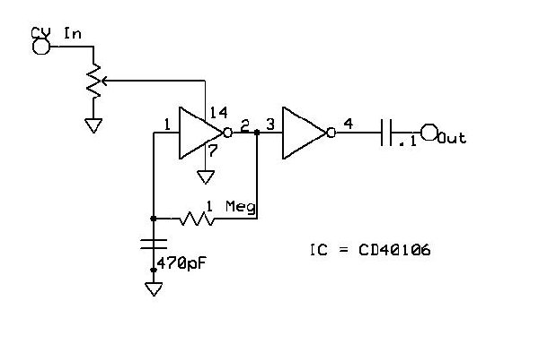
Now, before starting with all those chips, I need more oscillators. I'm thinking on making this Synthmonger ramp VCO shown here:
http://electro-music.com/forum/viewtopic.php?highlight=vco&t=28799
Or maybe this simple Oscillators from Bugbrand:
http://electro-music.com/forum/topic-23878.html&highlight=vco
Which kind of oscillator would be better for using it with 4051's melody generators, and 4017 sequencers, etc? I'm not sure if Synthmonger's VCO will work with that circuits. I want to have the possibility of making some kind of melodies with the oscillators. Would I need a "standard" analog sequencer to make the VCO work, or will it work with Lunetta style arpeggiators and "sequencers". I guess I will try both of them.
And, on the other side, will the Bugbrand oscillators accept 4051's (etc) melody generators and sequencers. If so, where do I connect them, in the "Sync" point at the input of the oscillator?
I'm very excited with all this. If Tjookum agrees, I will join the beginner's thread and post there my doubts and successes. That will generate a good amount of information for people which want to begin and it's in the same situation. |
|
|
Back to top
|
|
|
adambee7
Joined: Apr 04, 2009
Posts: 420
Location: united kingdom
|
| Posted: Tue Jun 08, 2010 2:46 am Post subject:
|
|
|
The synthmonger vco is really good. I've made both linear and expo ones. With the expo I added an inverter for a reverse ramp to ramp and also added a ramp to triangle converter. The linear i use for reverse and non reverse ramp lfo. I have just started a you tube chanel with the expo version being used along with a 4017 sequencer. The bass sounds are the tri wave.
http://www.youtube.com/user/TheAdambee7 |
|
|
Back to top
|
|
|
Silesius
Joined: Feb 12, 2010
Posts: 65
Location: Berlin
|
| Posted: Tue Jun 08, 2010 5:17 am Post subject:
|
|
|
Very interesting videos Adambee! I would like to know: you are using an envelope to achieve that sounds. Is that circuit easy and more or less compatible with my 9v single supply Lunetta? Also, I will make only the linear version, because I don't want to use a bipolar power supply. Would it be possible to make the nice sequences you make with your setup? Or that is more like an "normal" analog modular synth? And, finally, will the linear version work with the Lunetta style sequencers and arpeggiators (4017, 4051, etc)?
Sorry for sucking information like I do, but this very interesting for me now. Thanks everybody for your help  |
|
|
Back to top
|
|
|
tjookum
Joined: May 25, 2010
Posts: 360
Location: Netherlands
Audio files: 26
|
| Posted: Tue Jun 08, 2010 8:44 am Post subject:
|
|
|
| Silesius wrote: | Thanks everybody for your replies! And, of course, a big thanks to Rykhaard for giving us his time and knowledge
There's too much information here; I will need some time to assimilate everything; but I have tried some tricks with great results. Thanks again.
Now that I know (more or less) how to put the modules together, it's time to build more of them.
Now, before starting with all those chips, I need more oscillators. I'm thinking on making this Synthmonger ramp VCO shown here:
http://electro-music.com/forum/viewtopic.php?highlight=vco&t=28799
Or maybe this simple Oscillators from Bugbrand:
http://electro-music.com/forum/topic-23878.html&highlight=vco
Which kind of oscillator would be better for using it with 4051's melody generators, and 4017 sequencers, etc? I'm not sure if Synthmonger's VCO will work with that circuits. I want to have the possibility of making some kind of melodies with the oscillators. Would I need a "standard" analog sequencer to make the VCO work, or will it work with Lunetta style arpeggiators and "sequencers". I guess I will try both of them.
And, on the other side, will the Bugbrand oscillators accept 4051's (etc) melody generators and sequencers. If so, where do I connect them, in the "Sync" point at the input of the oscillator?
I'm very excited with all this. If Tjookum agrees, I will join the beginner's thread and post there my doubts and successes. That will generate a good amount of information for people which want to begin and it's in the same situation. |
I was thinking along the same lines, the standard 40106 square wave is good, but expanding my range of waveforms before getting into more modules seems a good plan. See the Eight Stage One-bit Custom Waveform Generator here: http://milkcrate.com.au/_other/sea-moss/ . I found it an easy build and very few parts required, but the waveform didn't deliver the results I was expecting. I think just a simple triangle and ramp wave used for LFO might be enough to get most sounds.
And ofcourse you are more than welcome to join in the discovery of lunetta-land. Im very interested to see your findings, keep tinkering.
_________________
There he goes. One of God's own prototypes. A high-powered mutant of some kind never even considered for mass production. Too weird to live, and too rare to die.
Hunter S. Thompson
movies
noise |
|
|
Back to top
|
|
|
adambee7
Joined: Apr 04, 2009
Posts: 420
Location: united kingdom
|
| Posted: Tue Jun 08, 2010 10:16 am Post subject:
|
|
|
| Silesius wrote: | Is that circuit easy and more or less compatible with my 9v single supply Lunetta? Also, I will make only the linear version, because I don't want to use a bipolar power supply. Would it be possible to make the nice sequences you make with your setup? Or that is more like an "normal" analog modular synth? And, finally, will the linear version work with the Lunetta style sequencers and arpeggiators (4017, 4051, etc)?
Sorry for sucking information like I do, but this very interesting for me now. Thanks everybody for your help |
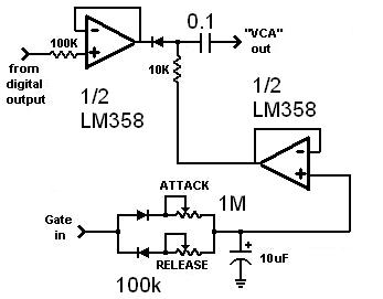
The VCA AR envelope is from Rykhaard and it uses a LM358 so it will work with single 9v rail. Good simple VCA.
The Linear and expo version will work with any CMOS shoved into it but i haven't tried shoving its output into anything apart from a VCA.
I would probably go for a normal 40106 osc if you wanted to control other CMOS from osc outs and sequence it using voltage starving. this is because you really want square waves for CMOS. Connect the CV out from 4017 sequencer (or other cmos) into CV in of voltage supply pin for the chip via a pot. |
|
|
Back to top
|
|
|
droffset

Joined: Feb 02, 2009
Posts: 515
Location: London area
Audio files: 2
|
|
|
Back to top
|
|
|
RF

Joined: Mar 23, 2007
Posts: 1502
Location: Northern Minnesota, USA
Audio files: 28
|
|
|
Back to top
|
|
|
tjookum
Joined: May 25, 2010
Posts: 360
Location: Netherlands
Audio files: 26
|
| Posted: Wed Jun 09, 2010 6:53 am Post subject:
|
|
|
Im definately adding that to my list of lunetta experiments, thanks!
_________________
There he goes. One of God's own prototypes. A high-powered mutant of some kind never even considered for mass production. Too weird to live, and too rare to die.
Hunter S. Thompson
movies
noise |
|
|
Back to top
|
|
|
Top Top

Joined: Feb 02, 2010
Posts: 266
Location: California
|
| Posted: Wed Jun 09, 2010 11:21 am Post subject:
|
|
|
| adambee7 wrote: |
The VCA AR envelope is from Rykhaard and it uses a LM358 so it will work with single 9v rail. Good simple VCA.
|
Is there a schem for this somewhere? It sounds nice in the vid... |
|
|
Back to top
|
|
|
adambee7
Joined: Apr 04, 2009
Posts: 420
Location: united kingdom
|
|
|
Back to top
|
|
|
Top Top
Joined: Feb 02, 2010
Posts: 266
Location: California
|
| Posted: Wed Jun 09, 2010 12:10 pm Post subject:
|
|
|
Ah, I see, it is like a combo of the diode VCA and AR generators with a dual op amp.
So can that be used with signals other than squarewaves? It seems you were using it with a triangle or saw wave VCO, right? |
|
|
Back to top
|
|
|
adambee7
Joined: Apr 04, 2009
Posts: 420
Location: united kingdom
|
| Posted: Wed Jun 09, 2010 12:29 pm Post subject:
|
|
|
| yeah its basically the same as what you used but with an opamp. The osc I used was the exp version of synthmongers VCO where I inverted the reversed ramp through a simple transistor inverter and then into a ramp to tri converter. |
|
|
Back to top
|
|
|
Rykhaard
Joined: Sep 02, 2007
Posts: 1290
Location: Canada
|
| Posted: Wed Jun 09, 2010 1:49 pm Post subject:
|
|
|
| adambee7 wrote: | | yeah its basically the same as what you used but with an opamp. The osc I used was the exp version of synthmongers VCO where I inverted the reversed ramp through a simple transistor inverter and then into a ramp to tri converter. |
Thanks for grabbing a copy of the schem. and posting it for me Adam!
If you wanted to use a bipolar waveform into it, just go with a bipolar opamp.
This one above is simple and works decently in a noise machine. |
|
|
Back to top
|
|
|
adambee7
Joined: Apr 04, 2009
Posts: 420
Location: united kingdom
|
| Posted: Wed Jun 09, 2010 2:02 pm Post subject:
|
|
|
| you can get some really nice violining effects out of it to at a slower tempo. |
|
|
Back to top
|
|
|
Silesius
Joined: Feb 12, 2010
Posts: 65
Location: Berlin
|
| Posted: Wed Jun 09, 2010 2:39 pm Post subject:
|
|
|
Ufff!! To much information here
Tjookum: I tried the custom wave generator, and it's nice, but I think it needs too much pots (they're expensive). Maybe the results are not exactly the same, but with the Bugbrand oscillators you can change the pulse width of the squarewaves. It gives interesting results and you don't need three ic's and eight pots. Try it, if you haven't done it yet (you're working a lot, man ).
And, regarding that YAVCO, I have just one (stupid, because it seems quite clear) question: you can only build one VCO per chip, isn't it? Or maybe two or three of them, but everything will be controlled by the same CV, right? Anyway, I will try it tonight.
And the last one (I don't want to abuse ). I really want to try that VCA/AR, but I have some doubts: what do i plug in the "gate" in, a clock or what? And what goes in the other input, a simple 40106 oscillator?
Finally, I have discovered that amazing Lunetta Document! It's incredible I haven't seen it before, because I'm absorbing everything I can from this forum. Thanks Droffset (and Inventor too!) for that great piece of job. I have printed it and I will be reading it these days. Hopefully, this will avoid more silly questions from me, at least for some days . |
|
|
Back to top
|
|
|
Ajax
Joined: Apr 05, 2010
Posts: 63
Location: San Francisco
|
| Posted: Wed Jun 09, 2010 3:17 pm Post subject:
|
|
|
| Silesius wrote: | ...but everything will be controlled by the same CV, right? Anyway, I will try it tonight.
...what do i plug in the "gate" in, a clock or what? And what goes in the other input, a simple 40106 oscillator? |
I think someone should start a CV thread, explain all of those workings... |
|
|
Back to top
|
|
|
Top Top
Joined: Feb 02, 2010
Posts: 266
Location: California
|
| Posted: Wed Jun 09, 2010 3:23 pm Post subject:
|
|
|
| Silesius wrote: | | I really want to try that VCA/AR, but I have some doubts: what do i plug in the "gate" in, a clock or what? And what goes in the other input, a simple 40106 oscillator? |
In the "from digital out" you plug your "audio" signal - any oscillator, sound source, etc...
In the GATE in, you plug any positive voltage source - it could be from a counter, a clock, even a switch/button wired to let your source voltage through when you press it.
A clock, if it is too fast, might not give you the best results, though then again, might give you something interesting. A "Gate" signal is generally just a sustained positive voltage.
The closer to the source voltage that your gate is, the more dynamic the action of the envelope generator will be. |
|
|
Back to top
|
|
|
|

 Forum index » DIY Hardware and Software » Lunettas - circuits inspired by Stanley Lunetta