| Author |
Message |
numbertalk

Joined: May 05, 2008
Posts: 992
Location: Austin, TX
Audio files: 5
|
 Posted: Fri Sep 26, 2008 12:04 pm Post subject:
bergfotron minimoog vca project(s) Posted: Fri Sep 26, 2008 12:04 pm Post subject:
bergfotron minimoog vca project(s) |
  |
|
Ok, let me start this post over (found answer to my initial calibration question).
I would like to build a Minimoog VCA clone. I would like to base this off of adaption(s) designed by Bergfotron. There are 2 of his schematics I'm looking at and would like to incorporate features of one into the other but have a few questions, if anyone could help (and can manage to read through these questions Smile).
For the questions below, schem 1 refers to http://hem.bredband.net/bersyn/VCA/VCA%20Minimoog%20Amore.png - this is the one I would like to mainly base my module on.
And schem 2 refers to http://hem.bredband.net/bersyn/VCA/VCA%20Minimoog.GIF - this is one I would like to use a few of the extra features from.
1) First off, on neither schematic does he include an input cap, before the TL072. Is this a problem for using this VCA for AC/audio signals? The original Minimoog VCA schematic shows a 330n cap at the input (along with a resistor, but I would like to add input pots anyway).
2) If I wanted to have 2 inputs as in schem 2, would I simply add to schem 1 the two 50K log pots with each pot's wiper leading to a 91K resistor for each? In schem 1 he has no resistor between the input signal and the TL072 at all.
3) In schem 1 the feedback loop of the input adder TL072 has a 100K resistor in parallel with a 10p cap but in schem 2 the feedback loop has just a resistor and its value is 150K. What is the difference and which would be better for this circuit (maybe for this one it boils down to a matter of taste but not sure how they differ)?
4) If I wanted to include the AM Offset control from schem 2 in schem 1, how would this be done? In schem 1 the base of the current sink transistor for VCA 1 is connected to ground through a 100K resistor. With AM offset in schem 2 that is replaced with a 10K pot with 1 lug connected directly to ground and another to +15VDC through a 4K7 resistor. Is that all I'd need to do - drop the 100K resistor and use these exact components instead?
5) The CV inputs in schem 1 each go through 2 stages of a dual op amp with 100K resistors in the feedback loops and 100K resistors between serial op amp stages. In schem 2 only the AM CV in goes through an op amp and it goes through only 1 stage of a TL072 - the ENV CV in doesn't go through an op amp at all. Do I just keep what's in schem 1 (each going through 2 op amps)?
6) If I wanted to add attenuators for the 2 CV inputs, would I model them on the AM Amount control in schem 2? -To be more specific, add a 50K pot to each CV input, connect it as show in schem 2 and add a 47K resistor between the incoming voltage and the inverting input of the op amp?
7) In schem 1 there is a 62K resistor between the AM mod stage and the VCA 1 current sink transistor but in schem 2 this is a 560K resistor. What's the difference and is this value influenced by whether or not you have the AM offset control I ask about in question 4 above?
8 He mentions "There is also some CV feedthrough that causes a slight click when very short attack times are used." Was this a problem in the original Minimoog VCA? What could I change to eliminate or control this?
Ok, I know that's more than plenty. I appreciate anyone patient enough to read through this, much less who can answer these questions for me. Thanks. |
|
|
Back to top
|
|
 |
Uncle Krunkus
Moderator

Joined: Jul 11, 2005
Posts: 4761
Location: Sydney, Australia
Audio files: 52
G2 patch files: 1
|
| Posted: Mon Sep 29, 2008 5:49 am Post subject:
|
|
|
I'll do my best with the ones I know,
1) This just comes down to AC or DC coupling. It won't effect the AC/Audio you put through it, but keep in mind that any DC bias will go through as well. DC coupling is probably the prefered default for a VCA, as they are sometimes used to process one CV with another CV. You could just include a switch so the option is left open.
2) I think so, but I'd need to study the schem a bit more to be sure.
3) The value of the feedback resistor will alter the gain of the adder. The 10pF across it is to stop high frequency oscillations, which sometimes happen if an op-amp is set for a gain above say 10. So the higher feedback resistor means less gain, and therefore the 10pF is not needed.
4) Not sure.
5) I'd stick with the 2 op-amp setup, only because it would offer more buffering. It may actually be closer to the original to leave the ENV CV unbuffered. Try breadboarding both to be sure I s'pose.
6) Yes, (about 95% sure)
7) Not sure.
 I'd say that a very short attack time is a slight click. You could try slowing the CV with a cap, but that would degrade the response of the whole unit. Sometimes the "limitations" of analogue circuits just need to be re-defined as "features". I'd say that a very short attack time is a slight click. You could try slowing the CV with a cap, but that would degrade the response of the whole unit. Sometimes the "limitations" of analogue circuits just need to be re-defined as "features".  
Hope this helps.
_________________
What makes a space ours, is what we put there, and what we do there. |
|
|
Back to top
|
|
|
numbertalk
Joined: May 05, 2008
Posts: 992
Location: Austin, TX
Audio files: 5
|
| Posted: Mon Sep 29, 2008 6:52 am Post subject:
|
|
|
| This helps a lot. Thanks so much for taking the time to answer what you could! |
|
|
Back to top
|
|
|
ultrashock

Joined: Dec 10, 2009
Posts: 40
Location: Vienna.AT
|
| Posted: Sat Dec 12, 2009 5:08 am Post subject:
|
|
|
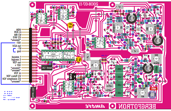
I'm upping this topic as I'm going to build this vcf+vca by Bergfotron, but I got cunfused a bit with the resistors values. Of course, I see the schemes aforesaid, but in the component placement file:
http://hem.bredband.net/bersyn/VCF/VCFPCB_k.pdf
the color decoding of resistors differs a bit from the common used color table. It will be very nice if you will post all the resistors' nominals used in this vcf+vca project, but if no, could you at least give me a solution how to "read" Jörgen Bergfors' color scheme of resistors?
Matching the R by this scheme http://www.breakup.de/resources/resistor.html I get 10 ohm values where should be placed 100K etc.
Of corse, the simpliest way is to rebuilt all the scheme from the original scheme from the beginning, but there are other projects in the web (for example, this minimoog vcf+vca built on smt elements
http://diyfactory.ru/forum/forums.html?act=Attach&type=post&id=4828) where all the values are specified.
but I really liked the Jorgen's PCB so I don't think that Bergfotron on his webpage was purposely made errors in PCB to prevent copypaste?
Last edited by ultrashock on Sat Dec 12, 2009 3:54 pm; edited 3 times in total |
|
|
Back to top
|
|
|
Sebo

Joined: Apr 27, 2007
Posts: 564
Location: Argentina
|
|
|
Back to top
|
|
|
ultrashock
Joined: Dec 10, 2009
Posts: 40
Location: Vienna.AT
|
|
|
Back to top
|
|
|
magman
Joined: Feb 04, 2009
Posts: 363
Location: Liverpool, UK
|
| Posted: Sat Dec 12, 2009 3:32 pm Post subject:
|
|
|
Looking at this circuit board I'm surprised that the apparent -15V connection apparently goes nowhere.
I would suggest that the lower *unused connection is actually the correct -15V connection. The 3S1 beads would then be just basic ferrite beads and the X2 resistors would be correct at 2R7 (2.7) Ohms. If you trace this *unused connection, it is connected to the - connections on the TLxxx opamps, which also reinforces the view that this is the proper -15V connection.
Looking at the original circuit diagram for the VCA, the X1 resistors should be 8R2 (8.2 ohms).
I would say that the confusing band on these resistors is actually silver, not white (compare the 910K resistor with X1), this may then be a multiplier of 0.01. Look at the 1% tolerance resistors on the resistor reference page sebo linked to:
http://www.hobby-hour.com/electronics/resistorcalculator.php
Hope this helps
Magman |
|
|
Back to top
|
|
|
ultrashock
Joined: Dec 10, 2009
Posts: 40
Location: Vienna.AT
|
| Posted: Sat Dec 12, 2009 4:15 pm Post subject:
|
|
|
Thank you very much for help! Everything clear with resistors for now and turned out as I supposed.
SR3 is a optocouple for resonance control
http://electro-music.com/forum/viewtopic.php?highlight=sr3&t=29839
2s1 bead - are ferrite beads (as one can use 10 ohm resistors instead (I saw them in Yusynth, for example)
the one point that still confuses me is -1V |
|
|
Back to top
|
|
|
Sebo
Joined: Apr 27, 2007
Posts: 564
Location: Argentina
|
| Posted: Sat Dec 12, 2009 7:06 pm Post subject:
|
|
|
Hi:
Go to the Bergfotron site and read the AMORE spec. You will find that the -1V
is a reference for VCOs, I don't know for what is used in this circuit.
In the AMORE spec there is a circuit to generate that -1V
The -15V connection is not showed in this layou because is masked by the header.
As I said before the resistors are 1%, so the last band SHOULD BE always
brown, so x2 is 27 ohms (is used for short circuit protection).
Also the multiplier band (BROWN one) is slightly wider in the layout (sadly
is not in the real resistors).
Don't use 10ohms resistors instead of the ferrite beads, as the 27 ohms are
in series. If you don't have ferrite beads use a jumper.
Hope this help.
_________________
Sebo
---------------------------------------
My Music:
https://www.facebook.com/cosaquitos/ |
|
|
Back to top
|
|
|
magman
Joined: Feb 04, 2009
Posts: 363
Location: Liverpool, UK
|
| Posted: Sun Dec 13, 2009 1:27 am Post subject:
|
|
|
Well spotted sebo.
I should have looked at the circuit board layout to check this, rather than just looking at the component placement.
Just to confirm for ultrashock, the -15V connection on the header is correct (there is a trace hidden by the header). The lower *unused connection is indeed unused.
I still read the X2 resistors as 2R7 (2.7 ohms) though, not 27R from the supplied colour coding. If this is correct, then I believe that the ferrite beads should be replaced by 10R (but better still, use the ferrite beads, as they can filter out some PSU noise from getting into the circuit), rather than a wire link.
Regards
Magman |
|
|
Back to top
|
|
|
ultrashock
Joined: Dec 10, 2009
Posts: 40
Location: Vienna.AT
|
|
|
Back to top
|
|
|
Sebo
Joined: Apr 27, 2007
Posts: 564
Location: Argentina
|
| Posted: Sun Dec 13, 2009 3:29 pm Post subject:
|
|
|
Hi magmans:
You are right x2 is 2R7. About the ferrite beads, they are for line filtering, and
sometimes are replaced by 10R resistors, because this resistors helps to
protect the components from short circuits (the resistor acts as a fuse). In this
case x2 is the resistor for short circuit protection, so another resistor is not
necessary.
Hi ultrashock:
About the 4053, I don't know exactly what this switch is doing, as the Bergfotron
have a lot of automation in it I suppose is for something to do with that, I will
look at the schematics later to see if I can understand why is connected to -1V
instead to GND. Anyway generating a -1V is a very simple task using a simple
resistor network.
_________________
Sebo
---------------------------------------
My Music:
https://www.facebook.com/cosaquitos/ |
|
|
Back to top
|
|
|
ultrashock
Joined: Dec 10, 2009
Posts: 40
Location: Vienna.AT
|
| Posted: Mon Dec 14, 2009 1:26 am Post subject:
|
|
|
Sebo, thanx for your help! Looking forward for your reply asap!
BTW, I've found out that 4053 is a triple analogical multiplexer/demultiplexer with 2 channels
then everything is right and -1V flows for range widening.. althought more voltage could be feed I think.... what do you think? |
|
|
Back to top
|
|
|
magman
Joined: Feb 04, 2009
Posts: 363
Location: Liverpool, UK
|
| Posted: Mon Dec 14, 2009 11:24 am Post subject:
|
|
|
I have a suspicion that the -1V trick may help to eliminate switching pops with the 4053, but I haven't been able to find any corroboration for this suspicion.
It should work with 0V as well, you can always try the -1V trick later.
Regards
Magman |
|
|
Back to top
|
|
|
|

 Forum index » DIY Hardware and Software