| Author |
Message |
jonasx26

Joined: Sep 20, 2009
Posts: 5
Location: Sweden
|
 Posted: Fri Nov 16, 2012 3:15 pm Post subject: Posted: Fri Nov 16, 2012 3:15 pm Post subject:
|
  |
|
Glad you found it useful!
I'm actually more familiar with single supply design than +/-, since I started out doing guitar effects (where 9V battery power is almost standardized.. )
Makes circuit design classes unnecessarily challenging 
Most jellybean op amps will be able to keep the VCC/2 voltage stable as long as the connected load is kept low enough. Max load (max output current) is specified in the op amp data sheets.
However, most op amps don't like driving capacitive loads. Best to avoid hooking up caps to the VCC/2 directly to be safe and make things easier.
It is possible to stabilize the VCC/2 buffer by adding freq. specific compensation inside of the feedback loop, but it gets somewhat complicated.
And in those cases it might be easier to use a proper +/- supply anyhow..
I also designed a voltage controlled exponential LFO for a pedal recently. Was quite tricky to get right. But it is certainly doable. Try a google search for "single supply op amp design" for some great design reference PDFs.
All the best! / Jonas
_________________
@jonasjberg Analog be harder than digital. |
|
|
Back to top
|
|
 |
analog_backlash

Joined: Sep 04, 2012
Posts: 393
Location: Aldershot, UK
Audio files: 21
|
| Posted: Fri Nov 16, 2012 3:34 pm Post subject:
|
|
|
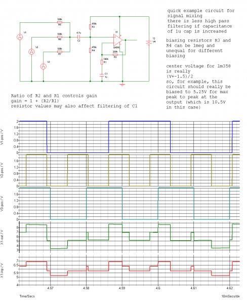
What I forgot to say in that last post is that the LFO had a mixer stage which could combine the trianglular and square parts of the output (actually ramp and pulse really, since the rise/high and fall/low parts of the waveform could be individually controlled). It was at the mixer stage that I was having the problems, which as I said, I now think I can understand. With both mixer controls in the "off" position, I didn't get the expected straight line on my scope, but a slightly "wobbly" line, deviating at the oscillator frequency.
I'll add this to my little list of things to do (which keeps getting longer...).
Cheers,
Gary |
|
|
Back to top
|
|
|
Uncle Krunkus
Moderator

Joined: Jul 11, 2005
Posts: 4761
Location: Sydney, Australia
Audio files: 52
G2 patch files: 1
|
| Posted: Fri Nov 16, 2012 5:58 pm Post subject:
|
|
|
I'll second that Gary.
Great link on the VC/2 op-amp stuff.
I could read through that over and over. It's a great quick check for heaps of things.
_________________
What makes a space ours, is what we put there, and what we do there. |
|
|
Back to top
|
|
|
JingleJoe

Joined: Nov 10, 2011
Posts: 878
Location: Lancashire, England
Audio files: 14
|
|
|
Back to top
|
|
|
analog_backlash
Joined: Sep 04, 2012
Posts: 393
Location: Aldershot, UK
Audio files: 21
|
| Posted: Thu Nov 29, 2012 11:42 am Post subject:
|
|
|
You're making up for lost time today Jingle Joe!
I have seen circuits like the one you've shown, but I was unsure as to how they worked exactly (hence I tended to stick to the inverting amp). I'll have to give this a try sometime. I have messed around with non-central reference voltages, usually because I wanted a set range of control voltage outputs but you need to be careful it doesn't swing too far one way or the other (and flatten out). Also, some op-amps work better than others, depending on the max/min voltage outputs it can produce (i.e. the output swing voltages).
As an aside, what software did you use to produce the schematic & simulation and does it cost any money? I can afford reasonably cheap software, but I prefer free!
Thanks,
Gary |
|
|
Back to top
|
|
|
JingleJoe
Joined: Nov 10, 2011
Posts: 878
Location: Lancashire, England
Audio files: 14
|
| Posted: Thu Nov 29, 2012 12:07 pm Post subject:
|
|
|
| analog_backlash wrote: |
As an aside, what software did you use to produce the schematic & simulation and does it cost any money? I can afford reasonably cheap software, but I prefer free!
Thanks,
Gary |
lucky for you I can't afford anything because i have no money ... shit! internet bills 
Anyways, Simetrix is what it's called, it was highly recommended by an old electronic engineer i knew 
I can see why too, it;s free and brilliant and the diagrams are industry standard.
It might be called simplis now but they are both the same really, there is a paid version which simulates larger circuits but I only encountered that problem when I was making a circuit with about 5 op amps in it. I just simulated them separately and bob is your uncle, it worked fine
_________________
As a mad scientist I am ruled by the dictum of science: "I could be wrong about this but lets find out"
Green Dungeon Alchemist Laboratories |
|
|
Back to top
|
|
|
analog_backlash
Joined: Sep 04, 2012
Posts: 393
Location: Aldershot, UK
Audio files: 21
|
| Posted: Thu Nov 29, 2012 1:02 pm Post subject:
|
|
|
| Brilliant! I'll give it a go. Thanks again. |
|
|
Back to top
|
|
|
Draal

Joined: May 18, 2010
Posts: 308
Location: Oak Park, IL
Audio files: 5
|
|
|
Back to top
|
|
|
analog_backlash
Joined: Sep 04, 2012
Posts: 393
Location: Aldershot, UK
Audio files: 21
|
| Posted: Sat Jan 05, 2013 3:34 pm Post subject:
|
|
|
Probably a "fair cop" there Draal. I think that we all jumped to the conclusion that it shouldn't work without actually trying it. It is an unusual circuit, but that doesn't mean it can't work.
I will try it out sometime, just for the record.
Gary |
|
|
Back to top
|
|
|
Draal
Joined: May 18, 2010
Posts: 308
Location: Oak Park, IL
Audio files: 5
|
| Posted: Mon Jan 07, 2013 2:31 pm Post subject:
|
|
|
No worries, I'm an odd duck so I gravitate to the "goofier" schematics. I am in the process of finishing up another lunetta and I'm at my mixer stage so I will doing a more typically biased single supply mixer.
I have bread boarded both my original version and the modified one and got similar sounding/performing mixers. However i'm inclined to agree that the mixer didn't fuss much due to only square waves being used.
For my particular setup, it works. But systems running voltages other than on/off square signals should follow your updated version of the mixer I posted.
Thanks for keeping me on my toes. 
Updated for clarity and respect.
_________________
Zontar Prevails! |
|
|
Back to top
|
|
|
analog_backlash
Joined: Sep 04, 2012
Posts: 393
Location: Aldershot, UK
Audio files: 21
|
| Posted: Wed Jan 09, 2013 4:19 pm Post subject:
|
|
|
Hi Draal,
I rather liked your "magic smoke" comment on the original post!  I'm a little bit "once bitten, twice shy" on relying on smoke (or at least the smell of hot semiconductors). For a TL082 (etc) it's not too much of a biggie, but when I first started playing with LM13700s, I seemed to be destroying them with (fairly) costly regularity (until I actually read a data sheet and found that 2mA is the maximum amp bias current I'm a little bit "once bitten, twice shy" on relying on smoke (or at least the smell of hot semiconductors). For a TL082 (etc) it's not too much of a biggie, but when I first started playing with LM13700s, I seemed to be destroying them with (fairly) costly regularity (until I actually read a data sheet and found that 2mA is the maximum amp bias current  ). I still have one that works on one side and not the other, but I don't know if it's safe to use the working part. I know that LM13700s are outside the Lunetta category, but if anyone knows the answer to that, I'd be interested to hear from them. ). I still have one that works on one side and not the other, but I don't know if it's safe to use the working part. I know that LM13700s are outside the Lunetta category, but if anyone knows the answer to that, I'd be interested to hear from them.
Gary |
|
|
Back to top
|
|
|
Draal
Joined: May 18, 2010
Posts: 308
Location: Oak Park, IL
Audio files: 5
|
| Posted: Thu Jan 10, 2013 6:05 am Post subject:
|
|
|
Looking back, I think this mixer was the first module I made for my Lunetta. Our 2nd child was due within a week or so and I was trying to get my lunetta up and running before the Diaper Wars started.
My schematic reading and assumptions were suspect at best during that period (you could still make that argument ) .
And yes, I do edit from time to time when I find my humor is not as funny the second go around.
_________________
Zontar Prevails! |
|
|
Back to top
|
|
|
prgdeltablues
Joined: Sep 25, 2006
Posts: 222
Location: UK
Audio files: 12
|
| Posted: Thu Jan 10, 2013 9:03 am Post subject:
|
|
|
I believe the mixer Draal posted (with the op-amp power pins being V+ and Gnd) works fine because the input signal only swings between V+ and Gnd. Op-amps don't like input swings that go outside the range of their power supply. Nothing to do with the square wave shape itself. It's only when your input signal swings above and below ground that your mixer op-amp needs a dual (+/-) supply.
Peter |
|
|
Back to top
|
|
|
analog_backlash
Joined: Sep 04, 2012
Posts: 393
Location: Aldershot, UK
Audio files: 21
|
| Posted: Fri Jan 11, 2013 2:59 am Post subject:
|
|
|
Thanks for that Peter. Yes, that does make sense since all of the CMOS outputs are positive only signals. My original reason for this thread was primarily that somebody pointed out that I was high-pass filtering my outputs to the mixer - see below (blue = [simulated]input, red = output):
http://electro-music.com/forum/phpbb-files/pre_post_mixer_170.png
I now know why this is (and I've remedied it), but the thread has rolled on. I'm not complaining, as it's all educational to me but (I think) that's why the square wave references might still be appearing here.
I appreciate any inputs on the subject.
Gary |
|
|
Back to top
|
|
|
|

 Forum index » DIY Hardware and Software » Lunettas - circuits inspired by Stanley Lunetta