| Author |
Message |
synthesist
Joined: Feb 17, 2011
Posts: 79
Location: austria
Audio files: 2
|
 Posted: Mon Jan 07, 2013 5:11 am Post subject:
cmos pwm ? Posted: Mon Jan 07, 2013 5:11 am Post subject:
cmos pwm ?
Subject description: maybe with transistor |
  |
|
hey !
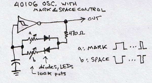
To change the pulsewidth on a 40106 oscillator you only need to place a diode on the input of the inverter, the other end goes to a variable resistor with its wiper placed to the inverter output.
but how can one modulate the PW? Did anyone try it with a resistor yet?
or is there any other way? |
|
|
Back to top
|
|
 |
RingMad

Joined: Jan 15, 2011
Posts: 429
Location: Montreal, Canada
Audio files: 4
|
|
|
Back to top
|
|
|
PHOBoS

Joined: Jan 14, 2010
Posts: 5881
Location: Moon Base
Audio files: 709
|
|
|
Back to top
|
|
|
elmegil

Joined: Mar 20, 2012
Posts: 2179
Location: Chicago
Audio files: 16
|
| Posted: Mon Jan 07, 2013 9:19 am Post subject:
|
|
|
| A & B could be a single dual pot with the two sides wired opposite each other as well. That would give a pretty smoothly changing transition of pulse width. |
|
|
Back to top
|
|
|
PHOBoS
Joined: Jan 14, 2010
Posts: 5881
Location: Moon Base
Audio files: 709
|
| Posted: Mon Jan 07, 2013 9:38 am Post subject:
|
|
|
| elmegil wrote: | | A & B could be a single dual pot with the two sides wired opposite each other as well. That would give a pretty smoothly changing transition of pulse width. |
that works, but the frequency will be fixed. You could add another pot in series but because of the pot for the
PWM control the range will be limited. And in turn it will influence the PWM control.
That's a nice thing about the standard saw/triangle + comparator combo,.
you have indepent frequency and pulse width control.
_________________
"My perf, it's full of holes!"
http://phobos.000space.com/
SoundCloud BandCamp MixCloud Stickney Synthyards Captain Collider Twitch YouTube |
|
|
Back to top
|
|
|
PHOBoS
Joined: Jan 14, 2010
Posts: 5881
Location: Moon Base
Audio files: 709
|
|
|
Back to top
|
|
|
Cynosure
Site Admin

Joined: Dec 11, 2010
Posts: 1025
Location: Toronto, Ontario - Canada
Audio files: 82
|
|
|
Back to top
|
|
|
JingleJoe

Joined: Nov 10, 2011
Posts: 878
Location: Lancashire, England
Audio files: 14
|
|
|
Back to top
|
|
|
Cynosure
Site Admin
Joined: Dec 11, 2010
Posts: 1025
Location: Toronto, Ontario - Canada
Audio files: 82
|
| Posted: Thu Aug 29, 2013 10:22 am Post subject:
|
|
|
| JingleJoe wrote: | | http://www.electro-music.com/forum/topic-55957.html |
I guess great minds think alike 
It is a pretty simple idea. I am sure that we aren't the only ones who thought of it.
_________________
JacobWatters.com |
|
|
Back to top
|
|
|
PHOBoS
Joined: Jan 14, 2010
Posts: 5881
Location: Moon Base
Audio files: 709
|
|
|
Back to top
|
|
|
jonasx26

Joined: Sep 20, 2009
Posts: 5
Location: Sweden
|
|
|
Back to top
|
|
|
trav

Joined: Sep 11, 2012
Posts: 108
Location: Auckland
Audio files: 16
|
| Posted: Sun Sep 01, 2013 2:13 pm Post subject:
|
|
|
| hey, I like that solution! sounds like what PHOBoS was thinking in his first post. use a multiplexor instead of S1 and you're in business. |
|
|
Back to top
|
|
|
PHOBoS
Joined: Jan 14, 2010
Posts: 5881
Location: Moon Base
Audio files: 709
|
| Posted: Mon Sep 02, 2013 7:30 am Post subject:
|
|
|
| trav wrote: | | hey, I like that solution! sounds like what PHOBoS was thinking in his first post. use a multiplexor instead of S1 and you're in business. |
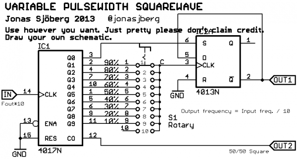
It is indeed similar to my initial idea. I think I actually have a version of that circuit in a book somewhere that uses 2 4017 counters,
so you can set the dutycyle with 2 rotary switches in steps of 1% instead of 10%. Of course for audiofrequencies it's nice if you can
sweep it without steps, but using a mux might create nice effects.
 control the mux(es) with a random generator for random pulsewidth control the mux(es) with a random generator for random pulsewidth 
_________________
"My perf, it's full of holes!"
http://phobos.000space.com/
SoundCloud BandCamp MixCloud Stickney Synthyards Captain Collider Twitch YouTube |
|
|
Back to top
|
|
|
PHOBoS
Joined: Jan 14, 2010
Posts: 5881
Location: Moon Base
Audio files: 709
|
Posted: Wed Sep 11, 2013 7:49 am Post subject:
PWM with a single XOR gate
Subject description: can easily be added to a CD4046 VCO |
|
|
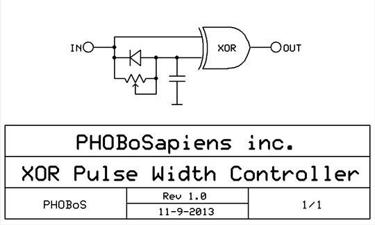
here's a method which I thought up while trying to sleep. (I count electrons not sheep).
I have a CD4046 VCO wired up with it's output (pin4) connected to the Internal Phase Comparator I (pin3), which is just an XOR. And at some
point I wondered what happens if you connect the output of the VCO to the signal input (pin14) which is the other input of the XOR. Well that
would mean that the inputs of the XOR are just shorted together and therefor it's output will always stay low. So not very intersting,..
But that got me thinking,. what if I delay one input ? Then the inputs would be different from each other for a short time and therefor it's output
will also be high for a moment. In other words I can control the pulse width. A simple adjustable delay can be made with a potentiometer and
a capacitor, and by adding a diode parallel to the potentiometer, the capacitor will get discharged instantly when the input goes low and so will
the output.
I did expect one problem, that is without a schmitt trigger input such a simple delay might not work so well, and cause unwanted oscillations.
So I just breadboarded it but I had to use an external XOR (CD4070) because I have the VCO build on a PCB and only made the XOR output
available. Well, it works perfect.  And the diode seems to take care of the unwanted behaviour I expected, without it I do see and hear some And the diode seems to take care of the unwanted behaviour I expected, without it I do see and hear some
extra oscillations.
The maximum 'on-time' is the same as the input signal and since the CD4046 has a pulse width of 50% I can't set it longer than
that. So with the right capacitor (dependent on the frequency) it's adjustable from 0 to 50%. But soundwise making it longer would sound
the same anyway. a 500K pot and 10nF capacitors seem to work nice.
fun fact: when I tried to adjust the circuit to work with NAND gates, I ended up with the same circuit I posted before. 
| Description: |
|
| Filesize: |
15.08 KB |
| Viewed: |
60840 Time(s) |
|
_________________
"My perf, it's full of holes!"
http://phobos.000space.com/
SoundCloud BandCamp MixCloud Stickney Synthyards Captain Collider Twitch YouTube |
|
|
Back to top
|
|
|
Cynosure
Site Admin
Joined: Dec 11, 2010
Posts: 1025
Location: Toronto, Ontario - Canada
Audio files: 82
|
| Posted: Wed Sep 11, 2013 12:20 pm Post subject:
|
|
|
A very ingenious and elegant solution. Nice work Phobos! 
_________________
JacobWatters.com |
|
|
Back to top
|
|
|
Psyingo

Joined: Jun 11, 2009
Posts: 248
Location: Canada
|
| Posted: Thu Sep 12, 2013 9:31 am Post subject:
|
|
|
| pulse width % will vary with frequency. these circuits provides constant pulse duration, so the timbre of the notes will change. with a cap in line with a pot to ground bass notes will sound very thin and reedy, while the higher you go the closer the pulse width percentage will be to 50%. close enough for jazz, though, amirite? |
|
|
Back to top
|
|
|
Cynosure
Site Admin
Joined: Dec 11, 2010
Posts: 1025
Location: Toronto, Ontario - Canada
Audio files: 82
|
| Posted: Thu Sep 12, 2013 10:45 am Post subject:
|
|
|
| Psyingo wrote: | | pulse width % will vary with frequency. these circuits provides constant pulse duration, so the timbre of the notes will change. with a cap in line with a pot to ground bass notes will sound very thin and reedy, while the higher you go the closer the pulse width percentage will be to 50%. close enough for jazz, though, amirite? |
Good point. It is probably ok for lunetta randomness or if you stay within a certain range, but will sound different as the frequency changes. I guess that is why a comparator on a saw wave is the most common method that I have seen.
It's just a pain to get a saw from a lunetta. The best method I have tested is a R2R ladder on all the outputs of a 4040, but that either requires a lot of resistors or a couple of (relatively) expensive ladder IC's.
_________________
JacobWatters.com |
|
|
Back to top
|
|
|
Psyingo
Joined: Jun 11, 2009
Posts: 248
Location: Canada
|
| Posted: Thu Sep 12, 2013 10:47 am Post subject:
|
|
|
could always try this:
you know how the quote goes... "Don't fear the opamp"
 |
|
|
Back to top
|
|
|
PHOBoS
Joined: Jan 14, 2010
Posts: 5881
Location: Moon Base
Audio files: 709
|
| Posted: Thu Sep 12, 2013 10:58 am Post subject:
|
|
|
yes I think you're correct. The pulse duration is set at a fixed time so if the frequency changes the pulse width will change too. And the pulse
duration will be a smaller % of one period at lower frequencies then at high frequencies. Of course without resquaring the signal it would just be a
passive highpass filter which would have a similar effect on the sound but it's not the same I think. (something with harmonics). So the thin and reedy
sound is in this case a result of changing the pulsewidth.
The circuits I came up work slightly different and work well with low frequencies. At least the first one was designed as an LFO the other one is
just an easy way to add pulse width control to a 4046 but can be used standalone and also works well with an LFO. But the pulse width does also
very with frequency. I don't think there is anyway around it unless you go for a different approach like a sawtooth oscillator + comparator.
edit: I think I need to type faster, this was a reply to psyingo's first post
_________________
"My perf, it's full of holes!"
http://phobos.000space.com/
SoundCloud BandCamp MixCloud Stickney Synthyards Captain Collider Twitch YouTube |
|
|
Back to top
|
|
|
PHOBoS
Joined: Jan 14, 2010
Posts: 5881
Location: Moon Base
Audio files: 709
|
|
|
Back to top
|
|
|
Psyingo
Joined: Jun 11, 2009
Posts: 248
Location: Canada
|
| Posted: Thu Sep 12, 2013 11:22 am Post subject:
|
|
|
| PHOBoS wrote: |
I would add a diode to create a saw instead of a triangle, else you don't just get pulse width control but phaseshifting aswell (unless that's a wanted feature).
well actually I'd just grab a quad opamp if I go that way, and leave out the 40106 completely. |
very very true. many ways to do it, and i hadn't considered the phasing issue. The OP referred to a 40106 oscillator, but you could do it any way. many ways to do the same thing. |
|
|
Back to top
|
|
|
SUGARAT
Joined: Jan 21, 2015
Posts: 19
Location: California
Audio files: 1
|
| Posted: Wed Feb 25, 2015 3:18 pm Post subject:
ANOTHER WAY! |
|
|
Another way to do it is to use a second osc to modulate the pulse width.
If you use a D flipflop and send one osc into the clock and the other into data and also XOR(XNOR?) it with the Q out, you will have a square wave with the period of one and the mark of the other.
Maybe not the best way if you need frequency and pw to always be synced or if you don't want to use a bunch of chips, but this way gives you a lot of control and makes some really crazy sounds if you hit it just right. |
|
|
Back to top
|
|
|
izash
Joined: Apr 22, 2010
Posts: 8
Location: Israel
|
Posted: Mon Feb 13, 2017 4:03 pm Post subject:
Re: PWM with a single XOR gate
Subject description: Solenoid Tambourine with PWM |
|
|
Dear Phobos,
Thank you for the elegant little PWM solution. It helped me so much to control the shuffle of my Solenoid Tambourine (see video below).
Now if you have a simple Voltage Controlled PWM trick up your sleeve for my Servo drum module...
Izhar
https://youtu.be/0pvNjgsVgSg
| PHOBoS wrote: | here's a method which I thought up while trying to sleep. (I count electrons not sheep).
The maximum 'on-time' is the same as the input signal and since the CD4046 has a pulse width of 50% I can't set it longer than
that. So with the right capacitor (dependent on the frequency) it's adjustable from 0 to 50%. But soundwise making it longer would sound
the same anyway. a 500K pot and 10nF capacitors seem to work nice.
|
[img][/img][url][/url] |
|
|
Back to top
|
|
|
PHOBoS
Joined: Jan 14, 2010
Posts: 5881
Location: Moon Base
Audio files: 709
|
|
|
Back to top
|
|
|
kaputtpanzer

Joined: Nov 02, 2009
Posts: 139
Location: Cologne
Audio files: 15
|
| Posted: Sun Nov 18, 2018 11:02 am Post subject:
|
|
|
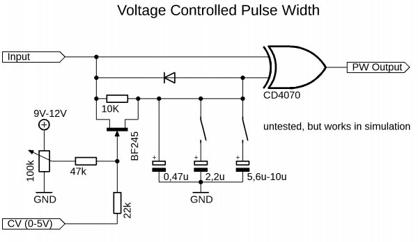
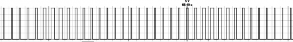
I added some rudimentary cv input to the xor pw controller. Works in simulation. I hope I find some time to breadboard this soon. The duty cycle range (which can be controlled by the control voltage) depends on the input frequency and the capacitance at the second input of the xor gate. With the additional capacitors and switches it should be possible to voltage control the duty cycle (~10-50%, maybe 50-90% with a nand gate instead a xor gate) over a relatively wide range of input frequencies. Not very elegant, but it should work just fine.
| Description: |
|
| Filesize: |
11.52 KB |
| Viewed: |
530 Time(s) |
| This image has been reduced to fit the page. Click on it to enlarge. |
|
| Description: |
|
| Filesize: |
32.27 KB |
| Viewed: |
506 Time(s) |
| This image has been reduced to fit the page. Click on it to enlarge. |
|
|
|
|
Back to top
|
|
|
|

 Forum index » DIY Hardware and Software » Lunettas - circuits inspired by Stanley Lunetta