| Author |
Message |
squarewhite
Joined: Jun 06, 2007
Posts: 82
Location: Asia
|
 Posted: Thu Apr 19, 2018 5:31 am Post subject:
Hacking a serial midi interface? Posted: Thu Apr 19, 2018 5:31 am Post subject:
Hacking a serial midi interface? |
  |
|
Hi,
I was just cleaning up my room and discovered that I still have a serial midi interface from Emagic. It was the first interface I ever use when using Opcode back in the 90s. It has served me well.
Fast forward--->
Now recently acquired a Digitakt and love the interface the possibilities of beats making. I might next acquired a tabletop polyphonic synth, maybe a Micromonsta or a preenfm2. So this discovery of this midi interface came as a blessing.. well maybe....
On the interface, it has a midi thru button. I plug my midi out from the Digitakt to the interface midi in and midi out from the interface to a Volca bass. Before doing this, I've already test that I could control the Volca Bass on track 9 of the Digitakt. So that works. But thru the midi interface nothing is transmitted.
So is there any way of hacking this to work as thru device? Maybe I need to power up the unit for it to work? Any ideas or suggestions?
There are 3 outs on this devices... hence if I get this working, it would be a super great bonus! and I can save money for one of the aforementioned synths!!
| Description: |
|
| Filesize: |
1.58 MB |
| Viewed: |
542 Time(s) |
| This image has been reduced to fit the page. Click on it to enlarge. |
|
| Description: |
|
| Filesize: |
1.76 MB |
| Viewed: |
562 Time(s) |
| This image has been reduced to fit the page. Click on it to enlarge. |
|
|
|
|
Back to top
|
|
 |
ian-s

Joined: Apr 01, 2004
Posts: 2672
Location: Auckland, New Zealand
Audio files: 42
G2 patch files: 626
|
| Posted: Fri Apr 20, 2018 9:14 am Post subject:
Re: Hacking a serial midi interface? |
|
|
| squarewhite wrote: | | Maybe I need to power up the unit for it to work? |
Probably, I don't think the optocoupler on the input will work without power. |
|
|
Back to top
|
|
|
squarewhite
Joined: Jun 06, 2007
Posts: 82
Location: Asia
|
| Posted: Sat Apr 21, 2018 2:53 am Post subject:
|
|
|
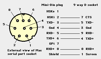
I was looking at the cable layout for the mac serial port connectors.. it seems that the connector has only 8 pins. and the pin for power is missing. My guess is that it the power is coming from the TX and RX port.
How and where can i get power into it the optocoupler?
i use this link for information on the serial ports.
https://whitefiles.org/b1_s/1_free_guides/fg1mt/pgs/h10b.htm |
|
|
Back to top
|
|
|
PHOBoS

Joined: Jan 14, 2010
Posts: 5873
Location: Moon Base
Audio files: 709
|
|
|
Back to top
|
|
|
squarewhite
Joined: Jun 06, 2007
Posts: 82
Location: Asia
|
|
|
Back to top
|
|
|
PHOBoS
Joined: Jan 14, 2010
Posts: 5873
Location: Moon Base
Audio files: 709
|
|
|
Back to top
|
|
|
squarewhite
Joined: Jun 06, 2007
Posts: 82
Location: Asia
|
| Posted: Sat Apr 21, 2018 5:09 am Post subject:
|
|
|
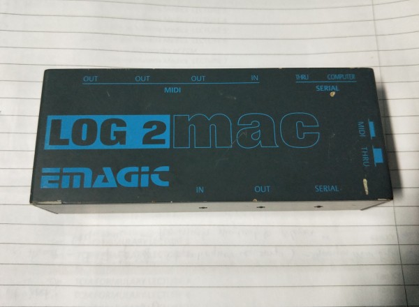
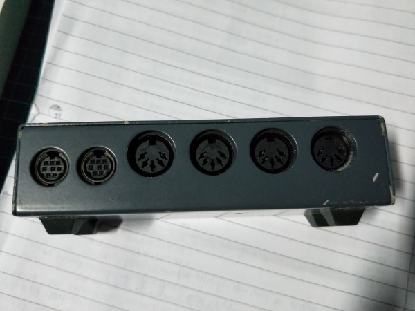
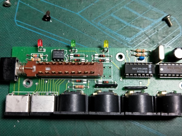
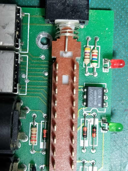
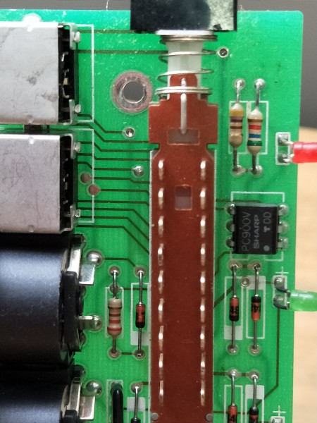
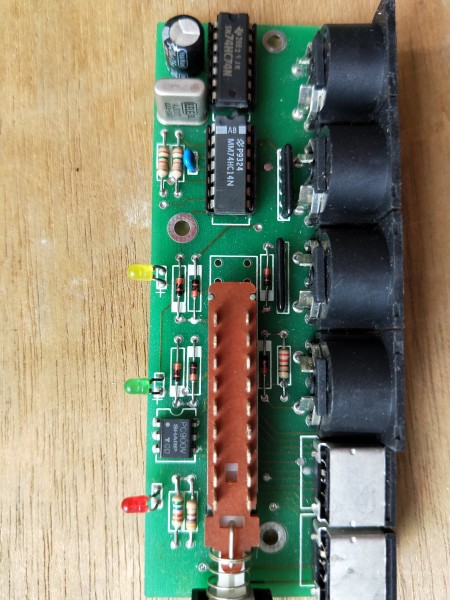
here are the pics...hopefully it's clear enough..
there's 3 ics, they are ,
Sharp RC900V
SN74HC74N
MM74HC14N
thanks for having a look at it.
| Description: |
|
| Filesize: |
4.51 MB |
| Viewed: |
537 Time(s) |
| This image has been reduced to fit the page. Click on it to enlarge. |
|
| Description: |
|
| Filesize: |
4.86 MB |
| Viewed: |
537 Time(s) |
| This image has been reduced to fit the page. Click on it to enlarge. |
|
| Description: |
|
| Filesize: |
3.78 MB |
| Viewed: |
541 Time(s) |
| This image has been reduced to fit the page. Click on it to enlarge. |
|
| Description: |
|
| Filesize: |
4.1 MB |
| Viewed: |
526 Time(s) |
| This image has been reduced to fit the page. Click on it to enlarge. |
|
|
|
|
Back to top
|
|
|
PHOBoS
Joined: Jan 14, 2010
Posts: 5873
Location: Moon Base
Audio files: 709
|
|
|
Back to top
|
|
|
squarewhite
Joined: Jun 06, 2007
Posts: 82
Location: Asia
|
| Posted: Sat Apr 21, 2018 5:48 am Post subject:
|
|
|
i couldn't find any info on the RC 900V chip.
The MM74HC14N is a hex inverter and the SN74HC74N is a trigger flip flop switcher. My very very rough guess is the -14N is for decoding and encoding the midi signals, the -74N is for the thru and not thru. That leaves the RC900V chip..
Yes I remember only when I plug the device to the mac serial port that I get the leds blinking on midi send or receive.
If it's possible to add power, I would like to add a simple circuit just to be able to power it from a 9v adapter.. likely have to use a TL 7805 voltage regulator for this or even better a 5v usb socket. But that would mean cutting a squarish hold for the plug... err.. going for the path of least resistance...  . .
well let me know if that's possible to get 5v on this! Would be super ace!!!
Thanks! |
|
|
Back to top
|
|
|
blue hell
Site Admin

Joined: Apr 03, 2004
Posts: 24489
Location: The Netherlands, Enschede
Audio files: 298
G2 patch files: 320
|
|
|
Back to top
|
|
|
squarewhite
Joined: Jun 06, 2007
Posts: 82
Location: Asia
|
| Posted: Sat Apr 21, 2018 6:56 am Post subject:
|
|
|
:facepalm:
time to get my eyes check!
ah ic...ok so I should be able to add power on pin 6 and 0V on pin 5? |
|
|
Back to top
|
|
|
blue hell
Site Admin
Joined: Apr 03, 2004
Posts: 24489
Location: The Netherlands, Enschede
Audio files: 298
G2 patch files: 320
|
| Posted: Sat Apr 21, 2018 8:40 am Post subject:
|
|
|
Dunno ..
Since there are no dedicated power pins the power is either obtained from a MIDI input or from the serial port connection. My guess would would be that the four diodes near the LEDs make a bridge rectifier and the electrolytic capacitor would buffer it ..
In that case your suspicion of the power coming from the RX signal would probably be right, and PHOBoS' idea that a connector could be used would be right as well ... would have to trace a couple of connections.
It might also come from the MIDI input, but in that case the thing should already work for what you want to do with it. Also in that case a bridge rectifier would not be needed but just a single diode would do (with the elco).
Anyways .. such are my guesses .. but its hard to track the copper traces from the images .. do you have a multimeter or a continuity tester?
And also .. when my guesses would be right connecting power to the opto coupler would not power the rest of the circuit .. as the bridge rectifier would block it .. I don' t know if any part of that would be needed .. but I'd be guessing that it would not be needed.
[Edit] the above paragraph is nonsense, sorry :-)
_________________
Jan
also .. could someone please turn down the thermostat a bit.
 |
|
|
Back to top
|
|
|
PHOBoS
Joined: Jan 14, 2010
Posts: 5873
Location: Moon Base
Audio files: 709
|
|
|
Back to top
|
|
|
squarewhite
Joined: Jun 06, 2007
Posts: 82
Location: Asia
|
| Posted: Sun Apr 22, 2018 3:00 am Post subject:
|
|
|
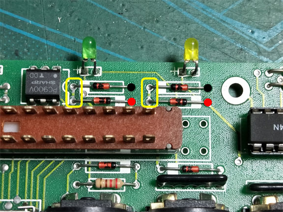
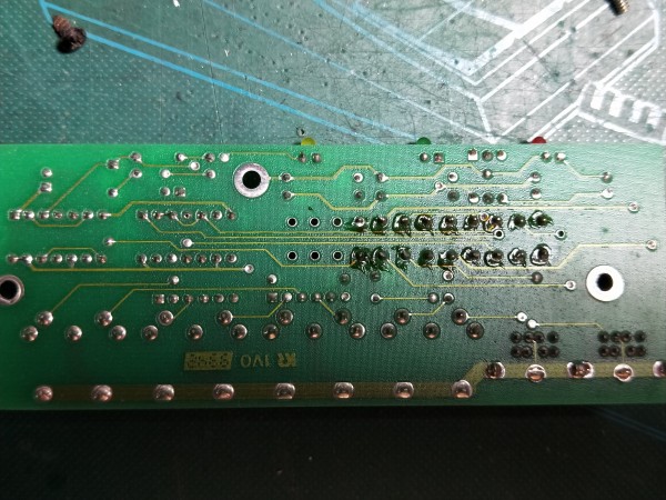
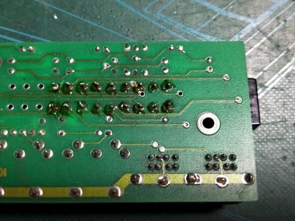
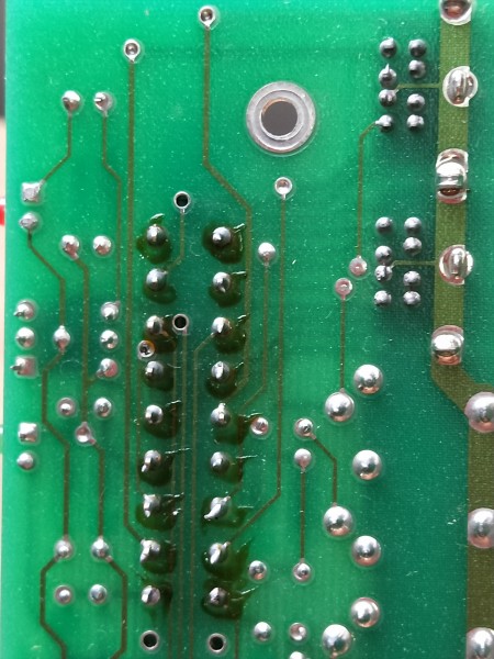
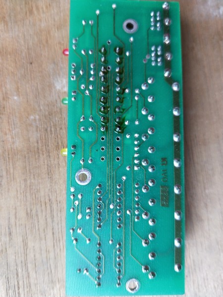
here are some better pics.. to help see the traces.
| Description: |
|
| Filesize: |
3.09 MB |
| Viewed: |
457 Time(s) |
| This image has been reduced to fit the page. Click on it to enlarge. |
|
| Description: |
|
| Filesize: |
3.27 MB |
| Viewed: |
461 Time(s) |
| This image has been reduced to fit the page. Click on it to enlarge. |
|
| Description: |
|
| Filesize: |
3.44 MB |
| Viewed: |
476 Time(s) |
| This image has been reduced to fit the page. Click on it to enlarge. |
|
| Description: |
|
| Filesize: |
3.51 MB |
| Viewed: |
466 Time(s) |
| This image has been reduced to fit the page. Click on it to enlarge. |
|
|
|
|
Back to top
|
|
|
PHOBoS
Joined: Jan 14, 2010
Posts: 5873
Location: Moon Base
Audio files: 709
|
| Posted: Mon Apr 23, 2018 6:49 am Post subject:
|
|
|
Even with the new photos it's still very hard to see how everything is connected wthout having the physical board in my hands.
It just doesn't really work well from a screen. However, I am pretty sure you can power it from the pads I circled or, probably better,
power it from 2 of the pads I marked black (gnd) and red (+5V). This way the power is blocked by the diodes to whatever it originally
derives the power from. An 78L05 should be sufficient as a regulator.
_________________
"My perf, it's full of holes!"
http://phobos.000space.com/
SoundCloud BandCamp MixCloud Stickney Synthyards Captain Collider Twitch YouTube |
|
|
Back to top
|
|
|
|

 Forum index » Instruments and Equipment » MIDI Controllers and Interfaces