| Author |
Message |
Bodega
Joined: Nov 02, 2008
Posts: 75
Location: Montreal
|
 Posted: Sat Feb 21, 2009 10:52 pm Post subject:
Can anyone suggest an LFO...? Posted: Sat Feb 21, 2009 10:52 pm Post subject:
Can anyone suggest an LFO...? |
  |
|
Hi all,
I'm looking to whip up a fairly simple LFO with just one knob - for rate. I'd like a triangle waveform with perhaps sine and pulse if that wouldn't complicate things unduly. They don't have to be simultaneously available.
Also, if possible, I'd like to be able to reset it with a footswitch, and it'll be powered by +/-15v.
Do those things sound like any LFO already out there?
Bonus points if I can use some of the 555s I have sitting around here. Though that's not a big sticking point, by any means.
thanks lots!
Matthew |
|
|
Back to top
|
|
 |
nicolas3141
Joined: May 25, 2007
Posts: 185
Location: Christchurch, New Zealand
|
|
|
Back to top
|
|
|
cthulu

Joined: Feb 07, 2009
Posts: 56
Location: Göteborg, Sweden
|
| Posted: Sun Feb 22, 2009 8:47 am Post subject:
|
|
|
First your ADSR and now this... I love your stuff man!  |
|
|
Back to top
|
|
|
Bodega
Joined: Nov 02, 2008
Posts: 75
Location: Montreal
|
| Posted: Sun Feb 22, 2009 9:29 am Post subject:
|
|
|
First off: Thanks! I've got all the parts here and I'm going to give it a go.
I had two quick questions, though:
1) where does the IN4004 go?
2) the point labelled "skew pot diodes" goes to *both* outside lugs of the 100k pot, does it? |
|
|
Back to top
|
|
|
e-grad
Joined: Sep 12, 2008
Posts: 142
Location: Berlin
|
| Posted: Sun Feb 22, 2009 10:43 am Post subject:
|
|
|
| 1N4004 links the pos. and neg. power rails. It's right below the legend posted. |
|
|
Back to top
|
|
|
ChrisR

Joined: Feb 22, 2009
Posts: 24
Location: Dark side of the room
|
| Posted: Sun Feb 22, 2009 10:54 am Post subject:
|
|
|
I like the skew function! Very usefull.
And thanks for posting a stripboard layout - good for clueless starters like me. 
Can the pulse and tri outs be used at the same time?
And why does putting LEDs in series lead to a higher voltage?
(Sorry if this is obvious)
Chris |
|
|
Back to top
|
|
|
nicolas3141
Joined: May 25, 2007
Posts: 185
Location: Christchurch, New Zealand
|
| Posted: Sun Feb 22, 2009 2:10 pm Post subject:
|
|
|
| Bodega wrote: |
1) where does the IN4004 go?
2) the point labelled "skew pot diodes" goes to *both* outside lugs of the 100k pot, does it? |
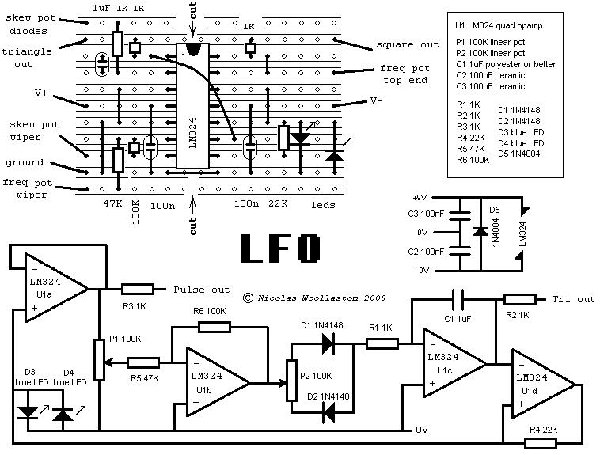
The 1N4004 is optional and just to protect the chip against a power supply reversal. I have missed it out on the stripboard layout, but if you want to add it, it goes across the chip from pin 11 to pin 4.
The wire labelled "skew pot diodes" goes to the junction of the two 1N4148s, which then go to outside lugs of the 100k pot. Look at the schematic.
Cheers,
Nicolas |
|
|
Back to top
|
|
|
nicolas3141
Joined: May 25, 2007
Posts: 185
Location: Christchurch, New Zealand
|
| Posted: Sun Feb 22, 2009 2:54 pm Post subject:
|
|
|
| Chris Rogue wrote: | Can the pulse and tri outs be used at the same time?
And why does putting LEDs in series lead to a higher voltage?
|
Both outputs can be used at the same time.
The voltage drop of the LEDs is used to set the voltage levels of the schmitt trigger. So replacing each LED with two in series doubles the voltage at which the thing switches over from charging the capacitor to discharging.
Cheers,
Nicolas |
|
|
Back to top
|
|
|
Bodega
Joined: Nov 02, 2008
Posts: 75
Location: Montreal
|
| Posted: Sun Feb 22, 2009 4:20 pm Post subject:
|
|
|
So I made it using what I had lying around, which was all the recommended values except for the LEDs - one's red and one's clear. The waveform is a bit "lopsided" as you'd expect.
Otherwise everything seems to do what it should so far except for the rate, which goes from about 1Hz up to about 8Hz.
Is that how it should be or have I missed something? Or could that be affected by the uneven LEDs? |
|
|
Back to top
|
|
|
nicolas3141
Joined: May 25, 2007
Posts: 185
Location: Christchurch, New Zealand
|
| Posted: Sun Feb 22, 2009 4:34 pm Post subject:
|
|
|
Yes a pair of blue or white LEDs will cause it to run about twice as slow as red. With a bit of tweaking it should be possible to get it to run from about 0.1 to nearly 10 Hz. The lack of range on the slow end you are seeing could be due to your speed pot not giving you a smooth taper all the way down to zero. Is it a good quality pot? To fine tune the range you can also reduce that 100K resistor (R6) to make it run a little slower.
Cheers,
Nicolas |
|
|
Back to top
|
|
|
Bodega
Joined: Nov 02, 2008
Posts: 75
Location: Montreal
|
| Posted: Sun Feb 22, 2009 5:01 pm Post subject:
|
|
|
0.1-10Hz would be great for my purposes.
The pot's a brand new Alpha. I'm inclined to think the problem is elsewhere.
I was having trouble with the pot cutting all sound at lower settings, so I removed the connection from the rate pot to the spot labelled "freq pot top end" and it seemed to get rid of that problem.
So right now the wiper is connected to "Freq pot wiper" and lug 3 is connected to the wire linking LEDs and Ground.
Maybe it's my "fix" that's causing the problem...?
Thanks for the help, btw! |
|
|
Back to top
|
|
|
nicolas3141
Joined: May 25, 2007
Posts: 185
Location: Christchurch, New Zealand
|
| Posted: Sun Feb 22, 2009 5:16 pm Post subject:
|
|
|
The three lugs of the speed/freq pot (P1) should be connected:
1 - to ground (ie D3/D4/U1b/U1c/C2/C3)
2 - to R5
3 - to R3/U1a
I don't quite understand where you currently have yours connected up to. It is possible that the stripboard diagram has an error, but the schematic is definitely correct, so if in doubt please refer to that.
Cheers,
Nicolas |
|
|
Back to top
|
|
|
Bodega
Joined: Nov 02, 2008
Posts: 75
Location: Montreal
|
| Posted: Sun Feb 22, 2009 10:58 pm Post subject:
|
|
|
Got it. I forgot to put in the jumper across the bottom of the IC socket. I also changed the LEDs to standard blue pair.
Now it works as it should with the recommended wiring for both pots.
Good stuff, Nicolas! |
|
|
Back to top
|
|
|
nicolas3141
Joined: May 25, 2007
Posts: 185
Location: Christchurch, New Zealand
|
|
|
Back to top
|
|
|
rubendelacosta
Joined: Dec 25, 2005
Posts: 153
Location: lisbon
|
| Posted: Tue Feb 24, 2009 9:09 am Post subject:
|
|
|
great!
i'll try it this week (probably)
do you think a capacitor and a switch could be add to get a low range mode?
something like this:
[img=http://img8.imageshack.us/img8/7346/semttulop.th.jpg]
edit: maybe a new topic should be created for your designs, they are kind of hidden in diferent topics |
|
|
Back to top
|
|
|
synthmonger
Joined: Nov 16, 2006
Posts: 578
Location: flada
Audio files: 3
|
| Posted: Tue Feb 24, 2009 10:05 am Post subject:
|
|
|
| Isn't the skew acting as a comparator? Couldn't ya stick a CV input on the U1A non-inverting input? |
|
|
Back to top
|
|
|
nicolas3141
Joined: May 25, 2007
Posts: 185
Location: Christchurch, New Zealand
|
| Posted: Tue Feb 24, 2009 12:57 pm Post subject:
|
|
|
Yes, good idea. You really need an extra opamp for that because you need to ensure that the U1a + input gets a voltage somewhere between roughly 0.1 and 0.7 times the voltage at the output of U1b (which is negative). Otherwise the thing won't oscillate. Symmetrical oscillation occurs when that ratio is 0.33. An extra opamp and a few diodes might do the trick. Or you could do it better with a multiplier like an LM13600.
Cheers,
Nicolas |
|
|
Back to top
|
|
|
Luka

Joined: Jun 29, 2007
Posts: 1003
Location: Melb.
|
|
|
Back to top
|
|
|
nicolas3141
Joined: May 25, 2007
Posts: 185
Location: Christchurch, New Zealand
|
|
|
Back to top
|
|
|
nicolas3141
Joined: May 25, 2007
Posts: 185
Location: Christchurch, New Zealand
|
| Posted: Fri Mar 06, 2009 4:04 am Post subject:
|
|
|
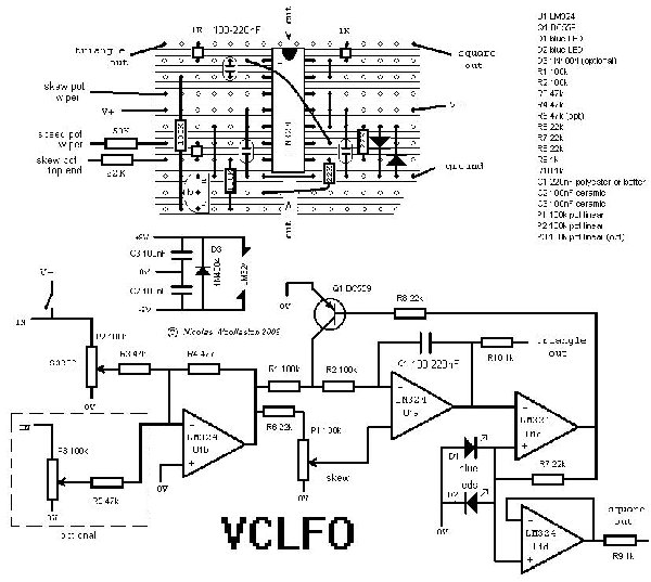
I have been thinking about the +/-15V question with regard to the VCLFO. It might be okay, but you may need to put in an additional protection diode for the transistor. At +/-9V supply it gets subjected to about 7V of reverse voltage which it seems to handle in practice, but is actually slightly in excess of what the datasheet recommends. With higher power supply voltages the extra reverse voltage might be too much for it.
Cheers,
Nicolas |
|
|
Back to top
|
|
|
Tim Servo

Joined: Jul 16, 2006
Posts: 924
Location: Silicon Valley
Audio files: 11
|
Posted: Sun Mar 08, 2009 1:41 am Post subject:
Can anyone suggest an LFO...?
Subject description: Servo's "8K" LFO |
|
|
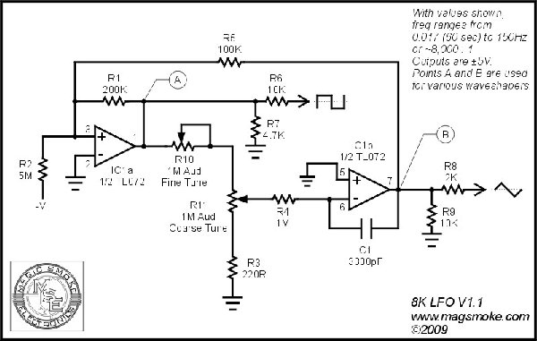
Here's one of the LFOs I've cooked up recently. This runs on a +/-15V supply and puts out standard +/-5V outputs. For the most part, it's a basic triangle oscillator built around a comparator and an integrator. I wanted something with a LOT more range than the other LFOs I was finding, so I made a few tweaks and came up with a design I really liked. This one goes from 0.017Hz (1 cycle / 60 seconds) to 150Hz, or a factor of 8,800:1 (hence the name).
A few points:
1) You can use Linear pots for the tuning controls, but it's MUCH easier to make fine changes in the lower portion of the range with Audio taper pots.
2) You can eliminate the Fine Tune control if you want. This reduces the range to 0.033Hz to 150Hz (approx 4,400 : 1) but this will probably do the trick for many applications.
3) The Fine Tune pot is set up so that it really does have less range than the Coarse Tune. When Coarse is at maximum, Fine will adjust from 50Hz to 150Hz. When Coarse is at minimum, Fine will adjust from 60 sec/cycle to 30 sec/cycle.
4) The timing cap can be found in polystyrene (23PS233 or 23PW233 from Mouser) if you want the best frequency stability, but you can also sub a film cap or other type. 3300pF works out to 3.3nF or .0033uF
I'll be making a few additions to this (sync, additional waveforms, Indicator LEDs), but the basic core will remain the same. Any thoughts?
Tim (got my LFO hat on) Servo
| Description: |
| Servo's 8K LFO - Updated with A and B points for waveshaper operation. |
|
| Filesize: |
73.21 KB |
| Viewed: |
3167 Time(s) |
| This image has been reduced to fit the page. Click on it to enlarge. |
|
Last edited by Tim Servo on Sun Mar 08, 2009 9:34 pm; edited 1 time in total |
|
|
Back to top
|
|
|
aerogramma

Joined: Feb 27, 2008
Posts: 156
Location: Roma, Italy - London, UK
Audio files: 13
|
| Posted: Sun Mar 08, 2009 7:53 am Post subject:
|
|
|
great stuff... i've been modifying LFOs with rotary switches > different capacitors to get more range... but this design is so compact you could easily add it to every module (like a mankato for example  ) for a nice self-contained object ) for a nice self-contained object
excellent for the one of us that build desktop modules (often to be found lying on the floor ) with a bit of free space left
thanks! |
|
|
Back to top
|
|
|
Tim Servo
Joined: Jul 16, 2006
Posts: 924
Location: Silicon Valley
Audio files: 11
|
Posted: Sun Mar 08, 2009 9:49 pm Post subject:
Can anyone suggest an LFO...?
Subject description: Servo's 8K Waveshapers |
|
|
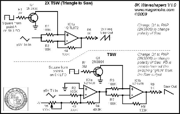
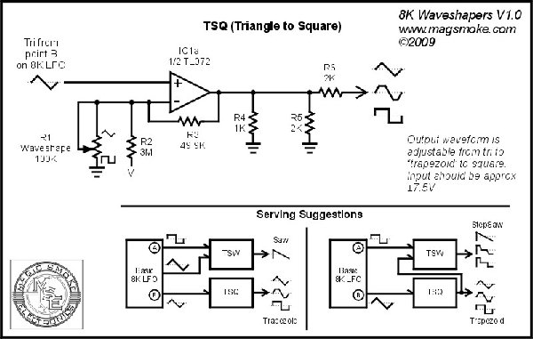
Here's a coupla add-ons for the 8K LFO. The first (TSW) uses the Tri and Square to make a Saw, or even a 2X Saw. The second (TSQ) takes a Tri and puts out a wave that is continuously variable from Tri to Square, with a "Trapezoid" shape in the middle. You can even take the output of the TSQ and put it into the TSW, and now you have a Tri to Square on one output and a Saw to Square on the other (both varied at the same time with the Waveshape control on the TSQ). By the way, a 1458 or other "low bandwidth" op amp works a little better for the TSW because it helps minimize the glitch in the reconstructed Saw output. I've got some more add ons that I'm still working on, but I thought I'd throw these out here because these variable outputs are so much fun.
Tim (also looks like a trapezoid in the middle) Servo
| Description: |
| Servo's 8K TSW (Triangle to Saw) Waveshaper |
|
| Filesize: |
97.82 KB |
| Viewed: |
2639 Time(s) |
| This image has been reduced to fit the page. Click on it to enlarge. |
|
| Description: |
| Servo's 8K TSQ (Triangle to Square) Waveshaper |
|
| Filesize: |
80.88 KB |
| Viewed: |
2450 Time(s) |
| This image has been reduced to fit the page. Click on it to enlarge. |
|
|
|
|
Back to top
|
|
|
v-un-v
Janitor


Joined: May 16, 2005
Posts: 8932
Location: Birmingham, England, UK
Audio files: 11
G2 patch files: 1
|
| Posted: Fri Mar 13, 2009 9:09 am Post subject:
|
|
|
Tim, could these waveshapers be used with Nicolas' simple VCO too?
http://www.electro-music.com/forum/topic-32689.html
_________________
ACHTUNG!
ALLES TURISTEN UND NONTEKNISCHEN LOOKENPEEPERS!
DAS KOMPUTERMASCHINE IST NICHT FÜR DER GEFINGERPOKEN UND MITTENGRABEN! ODERWISE IST EASY TO SCHNAPPEN DER SPRINGENWERK, BLOWENFUSEN UND POPPENCORKEN MIT SPITZENSPARKSEN.
IST NICHT FÜR GEWERKEN BEI DUMMKOPFEN. DER RUBBERNECKEN SIGHTSEEREN KEEPEN DAS COTTONPICKEN HÄNDER IN DAS POCKETS MUSS.
ZO RELAXEN UND WATSCHEN DER BLINKENLICHTEN. |
|
|
Back to top
|
|
|
Tim Servo
Joined: Jul 16, 2006
Posts: 924
Location: Silicon Valley
Audio files: 11
|
| Posted: Fri Mar 13, 2009 11:07 am Post subject:
Can anyone suggest an LFO...? |
|
|
Hey V,
These waveshapers should work with just about any triangle core oscillator. The TSW and the 2XTSW expect a +/-5V input, and need the square wave to be 90 degrees out of phase with the triangle (which happens naturally in integrator/comparator triangle cores). This also works with our 566-based TH-101 VCO (as this is how I generate the saw output). I don't know if the TSW would work with 555-based oscillators, but my guess would be 'yes.' The TSQ works best with an input a little hotter than the standard levels, so I tapped a +/-7.5V triangle from the 8K core. BTW, I'm working on voltage control for the waveshape on the TSQ. So far I have it working very nicely with a Vactrol, but I want to see if I can get an FET or perhaps a VC current sink to also do the job. Stay tuned.
Tim (90 degrees out of phase with reality) Servo |
|
|
Back to top
|
|
|
|

 Forum index » DIY Hardware and Software