| Author |
Message |
HexInverter

Joined: Aug 21, 2010
Posts: 338
Location: Canada
|
 Posted: Thu Aug 25, 2011 9:04 am Post subject: Posted: Thu Aug 25, 2011 9:04 am Post subject:
 sympleSEQ -- the simple to build analog step-sequencer [PCB] sympleSEQ -- the simple to build analog step-sequencer [PCB]
Subject description: Because you can never have too many sequencers! [kits available] |
  |
|
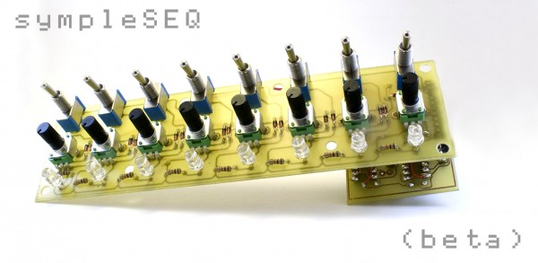
sympleSEQ -- the simple to build analog step-sequencer -- PCBs and kits available!

(PROTOTYPE SHOWN ABOVE)
UPDATES (scroll down for the rest of the post)
November 30, 2011 -- Everyone's pre-orders have shipped! Build manual coming soon 
September 5, 2011 -- I am very pleased to announce that Ben Marshall of Re:Synthesis / bigbluewave.co.uk will be offering custom etched, silk-screened panels for the sympleSEQ! Perhaps fully assembled modules as well! Awesome.
September 4, 2011 -- Uploaded a graphical rendering of the two finished boards. I will be making another prototype once my parts arrive, and will shoot a video of it.
August 30, 2011 -- I have successfully re-designed the logic board to be exactly 41mm wide, just like the control board! This means people using MOTM/synthesizers.com formats can place a sympleSEQ vertically in 1U wide panel space!  Beta #2 will be under-way soon, and then I will have some new pictures for all to see, and a video as well! Beta #2 will be under-way soon, and then I will have some new pictures for all to see, and a video as well!
August 29, 2011 -- Bill of materials is posted, thanks to Google Docs (no sign in necessary of course - link below!)
https://docs.google.com/spreadsheet/ccc?key=0AvD8ZRA_UZL8dEFER2dMWXFmVWs5cE11ZnYyVF9LVnc&hl=en_US
August 26, 2011 -- The design/layout is currently being altered to have selectable reset from steps 2-8 via the toggle switches that you also select gate on/off with. This will not change the complexity of assembly.

Greetings folks!
I am pleased to offer a PCB/kit design which I have slaved over for the past while for a simple Baby10-esque sequencer. I noticed a huge market hole for a simple to assemble sequencer, and thus sought out to design one that is both easy to build, and does away with all of the unnecessary frills associated with common sequencer designs.
The idea is simple:
BASE FEATURES:
- 8 steps of buffered CV/Gate out
- Actual note end per step (to make use of envelope generators -- the baby10 usually ties gates together)
- Select the length of sequence from 2-8 steps via the same switches used to toggle gate on/off. This does not complicate the assembly process any more than not having it
- CV / Gate out to interface with standard analog gear
- Most importantly: EASY TO BUILD!
OPTIONAL FEATURES:
- The option is there to easily add ext clocking (CMOS level - compatible with the MFOS 16 step and others I am sure)
- The option is there to add external/switch controlled Reset -- external stop is in beta phase and may or may not be included in the final design suggestion.
BILL OF MATERIALS:
Update: Bill of materials is posted, thanks to Google Docs (no sign in necessary of course - link below!)
https://docs.google.com/spreadsheet/ccc?key=0AvD8ZRA_UZL8dEFER2dMWXFmVWs5cE11ZnYyVF9LVnc&hl=en_US
My design makes use of commonly available (in Canada/US) board mount parts for the control board, and only needs 3 components wired off board -- tempo/clock knob, and two jacks/connectors of your choosing (for CV and Gate). This makes it extremely easy to put it together -- snap the parts in, go nuts with the soldering iron, and blam-o! Done!
The design is extremely compact and is intended to be used for Eurorack modulars or other places where space is limited.
It is also scalable (you can have many running off the same clock -- but only 8 steps maximum, sorry!), and includes full instructions for doing so.
Parts are commonly available, and I offer different kit complexities for different levels of builders (or laziness  ) )
I have organized an IndieGoGo.com campaign in order to facilitate easy purchasing of quantity discount volumes to make the project cheaper for everyone!
IndieGoGo accepts PayPal as well as credit cards, and is secure and easy to deal with for your pre-orders!
I will maintain this thread as a question answering forum and progress updates for everyone to see! If you can think of anywhere else that you may like to know about this, please do not hesitate to let them know! I would be most pleased!
Please go to the IndieGoGo campaign for a more detailed description of everything, and for pre-ordering!...
http://www.indiegogo.com/sympleSEQ
PS: Here are some images of my beta build of it! Note that I had to hand-route the second layer, and mount the headers awkwardly. Thus, my alignment is off. The production PCBs will be perfect, so that is not the case with them.
Also, I did not screw mine into the front panel, so the components are not quite aligned perfectly. I had to hastily get it ready for photos before my girlfriend left out of town (she's the photographer )
Yours will of course be much prettier than mine![img][/img]
| Description: |
|
| Filesize: |
303.68 KB |
| Viewed: |
537 Time(s) |
| This image has been reduced to fit the page. Click on it to enlarge. |

|
| Description: |
|
| Filesize: |
314.52 KB |
| Viewed: |
399 Time(s) |
| This image has been reduced to fit the page. Click on it to enlarge. |
|
| Description: |
|

Download (listen) |
| Filename: |
sympleSEQ_BOM.pdf |
| Filesize: |
66.44 KB |
| Downloaded: |
698 Time(s) |
Last edited by HexInverter on Wed Nov 30, 2011 6:25 pm; edited 14 times in total |
|
|
Back to top
|
|
 |
HexInverter
Joined: Aug 21, 2010
Posts: 338
Location: Canada
|
| Posted: Thu Aug 25, 2011 9:06 am Post subject:
|
|
|
| PS: I will be posting the bill of materials and instruction manual shortly as I finish it -- it is a very standard list of materials that most builders should have on hand if they're considering the minimal kits already! |
|
|
Back to top
|
|
|
Dan Lavin

Joined: Nov 09, 2006
Posts: 649
Location: Spring Lake, Mi, USA
Audio files: 21
|
| Posted: Thu Aug 25, 2011 10:18 am Post subject:
|
|
|
Looks nice, Hex! Can you advise the pot/switch/led board dimensions? I could guestimate, but I usually end up wrong when I do that.
_________________
Synth DIY since 1977! |
|
|
Back to top
|
|
|
HexInverter
Joined: Aug 21, 2010
Posts: 338
Location: Canada
|
| Posted: Thu Aug 25, 2011 10:21 am Post subject:
|
|
|
| Dan Lavin wrote: | | Looks nice, Hex! Can you advise the pot/switch/led board dimensions? I could guestimate, but I usually end up wrong when I do that. |
Thanks man!
Oh yes, those are cleverly hidden on the IndieGogo page at the bottom (with all the pretty vector renderings of it) -- GAH! Actually I just realized a chunk of the diagram containing the measurement got goofed up when I copy+pasted Fixing that now...
The board measures 161x41mm, but you also have to select a place for CV/Gate jacks and your clock/tempo knob.
It is extremely small. That is the idea I actually like the look of the pots without knobs -- they have a pointer on them as you can see, and add to the minimalist style.
Were you to use knobs, the maximum comfortable diameter of the knob (on the outside, like the actual SIZE of the knob) should be 19mm. More than that will mean they could be touching each other!
Last edited by HexInverter on Wed Oct 19, 2011 9:41 am; edited 1 time in total |
|
|
Back to top
|
|
|
Dan Lavin
Joined: Nov 09, 2006
Posts: 649
Location: Spring Lake, Mi, USA
Audio files: 21
|
| Posted: Thu Aug 25, 2011 11:24 am Post subject:
|
|
|
Hex: The external jacks and pot don't bother me. I was considering using a 1u rack panel which is 44.5mm wide....so at 41mm, it should squeek by.
Now, to find a 1u space in my full modular! 
_________________
Synth DIY since 1977! |
|
|
Back to top
|
|
|
HexInverter
Joined: Aug 21, 2010
Posts: 338
Location: Canada
|
| Posted: Thu Aug 25, 2011 11:27 am Post subject:
|
|
|
| Dan Lavin wrote: | Hex: The external jacks and pot don't bother me. I was considering using a 1u rack panel which is 44.5mm wide....so at 41mm, it should squeek by.
Now, to find a 1u space in my full modular! |
Oh! Vertical!!! Now there's an idea
EDIT: Ugh, sorry. I stupidly missed the inclusion of the logic board that mounts on the back. THAT board will make the width 51mm  I will update the drawing to show that. That just means you won't be able to piggy back the board onto the control board with the header as intended. You'd have to run short wires or bend things around so you can alter its position a bit. I will update the drawing to show that. That just means you won't be able to piggy back the board onto the control board with the header as intended. You'd have to run short wires or bend things around so you can alter its position a bit.
Sorry about that! |
|
|
Back to top
|
|
|
ericcoleridge

Joined: Jan 16, 2007
Posts: 889
Location: NYC
|
| Posted: Thu Aug 25, 2011 12:16 pm Post subject:
|
|
|
| so, there's a gate and CV at each step-- does that mean they could be brought out to separate outs? particularly the gates? |
|
|
Back to top
|
|
|
HexInverter
Joined: Aug 21, 2010
Posts: 338
Location: Canada
|
| Posted: Thu Aug 25, 2011 12:29 pm Post subject:
|
|
|
| ericcoleridge wrote: | | so, there's a gate and CV at each step-- does that mean they could be brought out to separate outs? particularly the gates? |
Well, the module is designed to output one summed CV, and one summed Gate for the whole channel. When I say "gate and CV per each step" I mean that each step generates a control voltage based on the rotational axis of the potentiometer for that step. At the same time, if the switch for that step is "ON", you get a gate pulse.
You could cut traces on the board and do some hacking to make it output a different one per step, yes, but then you would have a different output jack for each step. Am I understanding what you're asking? |
|
|
Back to top
|
|
|
emdot_ambient
Joined: Nov 22, 2009
Posts: 667
Location: Frederick, MD
|
| Posted: Thu Aug 25, 2011 1:27 pm Post subject:
|
|
|
From the pics at the bottom of all the various versions it looks like there's no Start/Stop switch...?
Also, how hard would it be to add a mod to run this off an external clock and/or pass the internal clock out?
I realize you're trying to keep it very simple (no step forward/backward or last step switch), but for most people's needs I'd think a Start/Stop and external/internal clock switch and clock in/out jack would be required to sync this with external modules.
_________________
Looking for a certain ratio since 1978 |
|
|
Back to top
|
|
|
HexInverter
Joined: Aug 21, 2010
Posts: 338
Location: Canada
|
| Posted: Thu Aug 25, 2011 1:42 pm Post subject:
|
|
|
| emdot_ambient wrote: | From the pics at the bottom of all the various versions it looks like there's no Start/Stop switch...?
Also, how hard would it be to add a mod to run this off an external clock and/or pass the internal clock out?
I realize you're trying to keep it very simple (no step forward/backward or last step switch), but for most people's needs I'd think a Start/Stop and external/internal clock switch and clock in/out jack would be required to sync this with external modules. |
It is already designed to pass clock out or to receive it in, as it is meant to be scalable The slashed out parts on the PCB layout of the smaller logic board are all like that to show to omit them when slaving to another sequencer.
There is no start/stop or forwards/back functionality. That would require an up/down counter which the 4017 is not. It can only count forwards as far as I know It would also further complicate things. It is intended to be programmed live. You could always add an on/off switch if you wish to program it before turning it on.
Clock in/out externally is easily doable, but would be considered a modification. It is designed to chain internally, but externally would require a couple of very minor additions (input protection diode, for instance) which are not included in this design. The pads are already there for it
It is a very basic design and is intended to be a ground for beginners to build upon and learn from.
Anyway, sending clock out is not the issue -- it will output a square wave clock at whatever +VCC you are powering it with, so it will interface with similar clock based sequencers such as the MFOS 16 step out of the box. In fact, the MFOS 16 step uses the same clock generator (CD40106), so as long as they are on the same +V they will interface just fine. |
|
|
Back to top
|
|
|
diablojoy

Joined: Sep 07, 2008
Posts: 809
Location: melbourne australia
Audio files: 11
|
| Posted: Thu Aug 25, 2011 2:39 pm Post subject:
|
|
|
when you say scalable i presume you mean for say a quad unit
it could be set up as a 32 step sequencer , 2 x 16 step or 4 x 8 steps
switchable perhaps ?
external clocking would be a must for me so good thing it would be easy to implement
definitely interested |
|
|
Back to top
|
|
|
HexInverter
Joined: Aug 21, 2010
Posts: 338
Location: Canada
|
| Posted: Thu Aug 25, 2011 2:45 pm Post subject:
|
|
|
| diablojoy wrote: | when you say scalable i presume you mean for say a quad unit
it could be set up as a 32 step sequencer , 2 x 16 step or 4 x 8 steps
switchable perhaps ?
external clocking would be a must for me so good thing it would be easy to implement
definitely interested |
Oh, no...unfortunately that is not what I mean.
I mean that you can build any number of 8 steps running off of the same clock.
Like I said, simplicity! This is supposed to be a no-frills design mainly intended for beginners, and as a simple control voltage source that can compliment an existing modular system with some simple sequences (filter cutoff and other modulations are some things that come to mind) while you might use your bad-boy, 32 step forwards/back, stop/reset sequencer for programming your main melodies - simple!
That is a great idea for the step amount scalability, but unfortunately it would be a whole 'nother project to do that, and much more complicated.
Perhaps sometime in the future when I am out of school and have loads of time?
Going above the 10 steps that are offered by the 4017 counter (reduced to 8 for this, since it is the most common usage of a 10-step) is actually a whole new world of design, and would revoke the "simple" status of this design which builds on the ever-faithful "Baby10" sequencer. |
|
|
Back to top
|
|
|
diablojoy
Joined: Sep 07, 2008
Posts: 809
Location: melbourne australia
Audio files: 11
|
| Posted: Thu Aug 25, 2011 2:57 pm Post subject:
|
|
|
| Quote: | | I mean that you can build any number of 8 steps running off of the same clock. |
ahh I see, should have realised that from the chip used
still it may not be too hard to acheive
I think i can see a way it could be accomplished
with some small additions , i will think on it over the weekend. |
|
|
Back to top
|
|
|
HexInverter
Joined: Aug 21, 2010
Posts: 338
Location: Canada
|
| Posted: Thu Aug 25, 2011 2:59 pm Post subject:
|
|
|
| diablojoy wrote: | | Quote: | | I mean that you can build any number of 8 steps running off of the same clock. |
ahh I see, should have realised that from the chip used
still it may not be too hard to acheive
I think i can see a way it could be accomplished
with some small additions , i will think on it over the weekend. |
Hmm, yeah, there has been talk about using a trigger on the last gate of one 4017 to start another counter, that sort of thing. |
|
|
Back to top
|
|
|
diablojoy
Joined: Sep 07, 2008
Posts: 809
Location: melbourne australia
Audio files: 11
|
| Posted: Thu Aug 25, 2011 6:47 pm Post subject:
|
|
|
yes my very brief thought was why not just try sequentially switching the clock every 8 pulses to the next seq in line ? It may require a 2nd sequential switch to avoid the extra cv from being outputted as the last seq stage may remain on but as you would probably sum the outputs of each seq to one overall output jack that part shouldnt be too difficult.
the more difficult part would be getting the timing and holding of the sequential switching right and that is where i am not so sure.
I think it may be workable but i need to check out quite a lot of things first. |
|
|
Back to top
|
|
|
HexInverter
Joined: Aug 21, 2010
Posts: 338
Location: Canada
|
| Posted: Thu Aug 25, 2011 6:49 pm Post subject:
|
|
|
| diablojoy wrote: | yes my very brief thought was why not just try sequentially switching the clock every 8 pulses to the next seq in line ? It may require a 2nd sequential switch to avoid the extra cv from being outputted as the last seq stage may remain on but as you would probably sum the outputs of each seq to one overall output jack that part shouldnt be too difficult.
the more difficult part would be getting the timing and holding of the sequential switching right and that is where i am not so sure.
I think it may be workable but i need to check out quite a lot of things first. |
Hmm, yeah, I wouldn't know how to approach the timing, either to be honest! |
|
|
Back to top
|
|
|
diablojoy
Joined: Sep 07, 2008
Posts: 809
Location: melbourne australia
Audio files: 11
|
| Posted: Fri Aug 26, 2011 12:55 am Post subject:
|
|
|
OK had a small epithany while having a coffee once i got home from work
I was struggling with the concept of latching a sequential switch for 8 clock pulses and then moving on to the next seq board, quite difficult for me at least . I then realised we actually dont need to do that.
if the sequential switching occurs on every clock pulse
the first clock pulse can go to the first seq board, the second clock pulse can go to the second seq board, the third clock pulse can go to the third board and so on . the CV output could be polled in the same manner at the same time . from in front of the panel it just means a differant way of numbering your steps.
there would need to be some processing of the clock
pulse width for various parts of the cct ie the output polling but that leads me to another interesting concept that i would need to think more about
concerning variable gate lengths.
doing it this way you could simply use a cd4017 and a few of dg412's similar to foniks sequential switch just expanded out , the switches duplicated and a fair bit of additional clock processing. using a 4017 it should be possible to do up to 64 steps using 8 seq boards, for those that like their projects on the larger size. 
A very simple to build 64 step sequencer with almost no panel wiring involved does sound incredibly interesting even with no extra features |
|
|
Back to top
|
|
|
inlifeindeath

Joined: Apr 02, 2010
Posts: 316
Location: Albuquerque, NM
|
|
|
Back to top
|
|
|
emdot_ambient
Joined: Nov 22, 2009
Posts: 667
Location: Frederick, MD
|
| Posted: Fri Aug 26, 2011 8:26 am Post subject:
|
|
|
| diablojoy wrote: | | ...I was struggling with the concept of latching a sequential switch for 8 clock pulses and then moving on to the next seq board, quite difficult for me at least... |
It doesn't sound that hard to me. Couldn't you just take the clock output and run it through a pulse divider set to divide by 8? Then pass that to the sequential switch. Result, every 8 pulses triggers the switch. Innit, eh?
_________________
Looking for a certain ratio since 1978 |
|
|
Back to top
|
|
|
emdot_ambient
Joined: Nov 22, 2009
Posts: 667
Location: Frederick, MD
|
| Posted: Fri Aug 26, 2011 8:41 am Post subject:
|
|
|
| HexInverter wrote: | | There is no start/stop or forwards/back functionality. That would require an up/down counter which the 4017 is not. It can only count forwards as far as I know It would also further complicate things. It is intended to be programmed live. You could always add an on/off switch if you wish to program it before turning it on. |
I'm not really worried about a forward/backward step function, but I would only consider getting one (or more) of these if a Stop and Reset function were easily doable.
It's not really a matter of how you program the sequence, but more how you sync the steps with external sequences. I mean, if I had 4 of these slaved together and was programming a pattern and I then switch on an external 8-step sequencer...even if their clocks are tied together...the new one's going to start at step 1, while the running one might be at step 11.
If you're doing melodic stuff this can lead to total madness and chaos. Not so important I suppose if you're only using them for filters or envelopes or something. But for melodic work, Stop/Start and Reset are essential, IMHO, of course.
_________________
Looking for a certain ratio since 1978 |
|
|
Back to top
|
|
|
HexInverter
Joined: Aug 21, 2010
Posts: 338
Location: Canada
|
| Posted: Fri Aug 26, 2011 9:12 am Post subject:
|
|
|
| emdot_ambient wrote: | | HexInverter wrote: | | There is no start/stop or forwards/back functionality. That would require an up/down counter which the 4017 is not. It can only count forwards as far as I know It would also further complicate things. It is intended to be programmed live. You could always add an on/off switch if you wish to program it before turning it on. |
I'm not really worried about a forward/backward step function, but I would only consider getting one (or more) of these if a Stop and Reset function were easily doable.
It's not really a matter of how you program the sequence, but more how you sync the steps with external sequences. I mean, if I had 4 of these slaved together and was programming a pattern and I then switch on an external 8-step sequencer...even if their clocks are tied together...the new one's going to start at step 1, while the running one might be at step 11.
If you're doing melodic stuff this can lead to total madness and chaos. Not so important I suppose if you're only using them for filters or envelopes or something. But for melodic work, Stop/Start and Reset are essential, IMHO, of course. |
Ahh yes, I see what you are saying
Hmm, maybe I am misunderstanding. Let's just clear up what you are asking. Here's what I can do -- is this right?...
For the "stop": Basically, we can have it so that jacks (or switches) on the front panel will allow you to throw pin 13 of the 4017 high -- that will cause it to pause, until the pin is thrown low once again (or that signal is removed) -- then it will continue to count. It's a pause/stop pin.
"Reset" is actually being implemented (see my post below), and with that, can also be manually reset by a push button switch, or a jack that you send a high signal to to reset it to the first step.
Is this the functionality you desire? If so, it is very easy to implement. It's basically already there. I will include instructions and put the pads on the board to run wires to do so
Last edited by HexInverter on Fri Aug 26, 2011 9:25 am; edited 1 time in total |
|
|
Back to top
|
|
|
HexInverter
Joined: Aug 21, 2010
Posts: 338
Location: Canada
|
| Posted: Fri Aug 26, 2011 9:14 am Post subject:
|
|
|
UPDATE!: The design/layout is currently being altered to have selectable reset from steps 2-8 via the toggle switches that you also select gate on/off with! A rather clever friend keyed me in on that idea (I don't know why it hasn't been done before, but it's very clever)
This does not change the complexity of the board or assembly. I will not be doing anything that revokes the "simple" status of this project.
Once it is done I will probably post a schematic for all to reference, and begin formal production of the bill of materials! |
|
|
Back to top
|
|
|
emdot_ambient
Joined: Nov 22, 2009
Posts: 667
Location: Frederick, MD
|
| Posted: Fri Aug 26, 2011 9:31 am Post subject:
|
|
|
YOU DUH MAN!
Yeah, that's exactly what I was after. Now this is looking like a very sweet project. 
_________________
Looking for a certain ratio since 1978 |
|
|
Back to top
|
|
|
HexInverter
Joined: Aug 21, 2010
Posts: 338
Location: Canada
|
| Posted: Fri Aug 26, 2011 9:38 am Post subject:
|
|
|
| emdot_ambient wrote: | YOU DUH MAN!
Yeah, that's exactly what I was after. Now this is looking like a very sweet project. |
YAY! That makes me happy. That is nothing to implement -- I just did it as we speak!
So yes, reset/stop can be considered a feature. I will update the feature-list in the proper channels. |
|
|
Back to top
|
|
|
HexInverter
Joined: Aug 21, 2010
Posts: 338
Location: Canada
|
| Posted: Fri Aug 26, 2011 11:55 am Post subject:
|
|
|
Uh-oh, I'm going to eat my words here, emdot_ambient.
Just tried it out on the breadboard and it's not behaving as anticipated.
The reset is definitely a go, but unfortunately with the stop/start, the gate and clock continue to pulse even when the 4017 is paused (d'uh...)
Sorry, I got a little excited Hold onto your cash until I've got this 100%, just in case There is PLENTY of time to wait to place your order, as they won't be made until after the funding cut off (60 days from now)
EDIT: pretty sure it just needs a bit of thought. I think I can do it still, I just want it to work perfectly of course. A few bits of logic from the spare 40106 should do the trick |
|
|
Back to top
|
|
|
|

 Forum index » DIY Hardware and Software
