electro-music.com   Dedicated to experimental electro-acoustic
and electronic music
 
    Front Page  |  Radio
 |  Media  |  Forum  |  Wiki  |  Links
Forum with support of Syndicator RSS
 FAQFAQ   CalendarCalendar   SearchSearch   MemberlistMemberlist   UsergroupsUsergroups   LinksLinks
 RegisterRegister   ProfileProfile   Log in to check your private messagesLog in to check your private messages   Log inLog in  Chat RoomChat Room 
go to the radio page Live at electro-music.com radio 1 Please visit the chat
poster
 Forum index » DIY Hardware and Software » Circuit Bending
portable tape player to tape sequencer
Post new topic   Reply to topic Moderators: dnny, v-un-v
Page 1 of 1 [10 Posts]
View unread posts
View new posts in the last week
Mark the topic unread :: View previous topic :: View next topic
Author Message
dnny


Joined: Mar 12, 2005
Posts: 519
Location: Helsinki, Finland
Audio files: 8

PostPosted: Fri Sep 30, 2005 4:42 pm    Post subject: portable tape player to tape sequencer Reply with quote  Mark this post and the followings unread

ok so since i saw this tape sequencers made by Gijs Gieskes

the one whit logic sequencing
Posted Image, might have been reduced in size. Click Image to view fullscreen.
and the one whit mecanical sequencing
Posted Image, might have been reduced in size. Click Image to view fullscreen.

i have wanted to make my own - and because Gijs has no information on those beasts.
( Gijs page)


finaly i choosed to go my own way . . . but i need some help

first i got this cheap portable casette player "unisef z-50". opend it up and tryed the motor - but i found out that on low voltage (slow playback) the motor doasent have the strenght to roll. so i savaged and old VCR. and found nice powerfull DC motors for the job - the problem whit the bigger motor is that it draws more current so i can´t draw the voltage straight from the chip as i planed in the first place - this is my first plan :
Posted Image, might have been reduced in size. Click Image to view fullscreen.

so now i have CV of about 0 to 7V

i have one of thease KEMO B 184 kits (adjustable PSU) that looks like this :
Posted Image, might have been reduced in size. Click Image to view fullscreen.
it gives the suffisent voltage to my new motor (0 - 14V)

so the final question is how to make this power supply controlled whit the controll voltage i get from my sequencer unit (0-7V)?

thanks in advance and sorry for this confusing post.

here is the motor whit the player:
Posted Image, might have been reduced in size. Click Image to view fullscreen.
daniel

and here are some mp3´s whit Gijs tape sequencer sounds


TapeSEQwithDoormouseAndLSDj.mp3
 Description:
tape sequencer whit doormouse + LSDj

Download
 Filename:  TapeSEQwithDoormouseAndLSDj.mp3
 Filesize:  1.84 MB
 Downloaded:  2475 Time(s)


TapeSEQwithGUITARandLSDj.mp3
 Description:
tape sequencer whit guitar +LSDj

Download
 Filename:  TapeSEQwithGUITARandLSDj.mp3
 Filesize:  1.93 MB
 Downloaded:  2469 Time(s)


_________________
Association of experimental electronics
www.koelse.org
flickr: cable porn group
Back to top
View user's profile Send private message Send e-mail Visit poster's website Yahoo Messenger
v-un-v
Janitor
Janitor


Joined: May 16, 2005
Posts: 8933
Location: Birmingham, England, UK
Audio files: 11
G2 patch files: 1

PostPosted: Fri Sep 30, 2005 5:22 pm    Post subject: Reply with quote  Mark this post and the followings unread

dnny,

those tracks are demented- well done :D

more?
Back to top
View user's profile Send private message Send e-mail
blue hell
Site Admin


Joined: Apr 03, 2004
Posts: 24075
Location: The Netherlands, Enschede
Audio files: 277
G2 patch files: 320

PostPosted: Fri Sep 30, 2005 5:48 pm    Post subject: Reply with quote  Mark this post and the followings unread

Especially the 2nd one has a weirdness that I like.

You're almost there, just multiply the control signal by a factor of two and add some 1.2 .. 1.4 Volts and then connect the output of that straight to the base of the darlington, deleting 220 R, 15 Volt zener, etc.

This multiplication by a constant and addition of an offset is standard opamp stuff as you've seen it in the soundlab already, probably.

When you want me to beam up a proposal just let me know & I'll photograph what I just sketched here.

_________________
Jan
also .. could someone please turn down the thermostat a bit.
Posted Image, might have been reduced in size. Click Image to view fullscreen.
Back to top
View user's profile Send private message Visit poster's website
dnny


Joined: Mar 12, 2005
Posts: 519
Location: Helsinki, Finland
Audio files: 8

PostPosted: Sat Oct 01, 2005 1:34 am    Post subject: Reply with quote  Mark this post and the followings unread

Blue Hell if you have the proposal ready - beam it up - please. so i can get this thing running - i know that im really close but still there is just this few things that i need to learn...

Quote:
those tracks are demented- well done Very Happy

more?


i did not make those tracks - i wish.
tracks are made by Gijs Gieskes
and yes there are more mp3´s from him
Gijs Gieskes mp3 page
the pages look like they have been bended - i have never seen a HTML-bend before Smile

_________________
Association of experimental electronics
www.koelse.org
flickr: cable porn group
Back to top
View user's profile Send private message Send e-mail Visit poster's website Yahoo Messenger
Uncle Krunkus
Moderator


Joined: Jul 11, 2005
Posts: 4761
Location: Sydney, Australia
Audio files: 52
G2 patch files: 1

PostPosted: Sat Oct 01, 2005 4:49 am    Post subject: Reply with quote  Mark this post and the followings unread

Gijs is a seriously out there kinda person.
The world needs more people like that.
Very cool.

_________________
What makes a space ours, is what we put there, and what we do there.
Back to top
View user's profile Send private message Visit poster's website
blue hell
Site Admin


Joined: Apr 03, 2004
Posts: 24075
Location: The Netherlands, Enschede
Audio files: 277
G2 patch files: 320

PostPosted: Sat Oct 01, 2005 7:06 am    Post subject: Reply with quote  Mark this post and the followings unread

Something like this I was thinking.

The first opamp amplifies the signal by a factor of minus two and it adds some offset that can be set by the pot (which I specified as R, but the 100 k pot of the original PSU will work as well).

The 2nd opamp makes the signal go positive again, a plain invertor.

The two capacitors tame the thing a bit. You might want to add a capacitor of something like 470 nF between the wiper of the offset pot and ground to make it less jumpy in case it's quality is not too good.

The opamp can be almost anything, I think the good old TL071 series is still in fashion these days - I saw it used in the soundlab I think ?

The only thing is it needs a dual power supply of about +/- 15 Volt, which might be a bit clumsy for this partiular purpose. But to get around that it goes beyond just a bit of sketching for me - I'd need to breadboard it.

Ideally for motor control you'd want to have some feedback involving the actual RPM's the motor makes, or the current that flows through it. A circuit without feedback will only get you sofar, but when the motor has enough power and the flywheel is big enough it might work.


001.jpg
 Description:
just a sketch
 Filesize:  151.79 KB
 Viewed:  42790 Time(s)

001.jpg


_________________
Jan
also .. could someone please turn down the thermostat a bit.
Posted Image, might have been reduced in size. Click Image to view fullscreen.
Back to top
View user's profile Send private message Visit poster's website
dnny


Joined: Mar 12, 2005
Posts: 519
Location: Helsinki, Finland
Audio files: 8

PostPosted: Sat Oct 15, 2005 3:50 am    Post subject: Reply with quote  Mark this post and the followings unread

thanks Blue Hell

i think thats too complicated and hi-end for me - i need something
lo-fi and simple.

i have thought to use light dependent resistor or light dependent transistor to feed the power supply darlington transistors base (shown on the pic as red spot) and have the CV from the sequencer unit to light up a LED that is coupled whit the light sensing component on the power circuit.
so the component should go between the pot and the base of the darlington tranny (the pot would function as master speed)
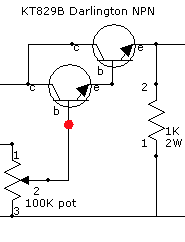
Posted Image, might have been reduced in size. Click Image to view fullscreen.

_________________
Association of experimental electronics
www.koelse.org
flickr: cable porn group
Back to top
View user's profile Send private message Send e-mail Visit poster's website Yahoo Messenger
mosc
Site Admin


Joined: Jan 31, 2003
Posts: 18195
Location: Durham, NC
Audio files: 211
G2 patch files: 60

PostPosted: Sat Oct 15, 2005 7:53 am    Post subject: Reply with quote  Mark this post and the followings unread

Dnny, this guy is too good. I posted something about him on Online Music, http://electro-music.com/forum/topic-8235.html If you know how to contact him, please let him know about it.
_________________
--Howard
my music and other stuff
Back to top
View user's profile Send private message Send e-mail Visit poster's website AIM Address
gsga


Joined: Jul 22, 2004
Posts: 267
Location: allentown, pa

PostPosted: Tue Nov 08, 2005 7:07 pm    Post subject: Reply with quote  Mark this post and the followings unread

I know little about electronics, but I'm psyched! I think I'm just going to crack open a walkman and start messing around with it.

On battery power, of course. Very Happy

_________________
"Pop music is for sheep and we are wolves disguised as shepherds."
Back to top
View user's profile Send private message Send e-mail Visit poster's website
deknow


Joined: Sep 15, 2004
Posts: 1307
Location: Leominster, MA (USA)
G2 patch files: 15

PostPosted: Tue Nov 08, 2005 9:50 pm    Post subject: Reply with quote  Mark this post and the followings unread

...in college, i had friends that did a lot of transcription of jazz solos (i did very few myself). tuning the particular recording to a piano, or even slowing things down to make it a little easier to hear the individual notes was a thing everyone wanted to do. i made a few bucks putting a hole in the right place to stick a screwdriver in and adjust the motor speed of various walkmen and boom boxes.

deknow
Back to top
View user's profile Send private message Send e-mail
Display posts from previous:   
Post new topic   Reply to topic Moderators: dnny, v-un-v
Page 1 of 1 [10 Posts]
View unread posts
View new posts in the last week
Mark the topic unread :: View previous topic :: View next topic
 Forum index » DIY Hardware and Software » Circuit Bending
Jump to:  

You cannot post new topics in this forum
You cannot reply to topics in this forum
You cannot edit your posts in this forum
You cannot delete your posts in this forum
You cannot vote in polls in this forum
You cannot attach files in this forum
You can download files in this forum


Forum with support of Syndicator RSS
Powered by phpBB © 2001, 2005 phpBB Group
Copyright © 2003 through 2009 by electro-music.com - Conditions Of Use