| Author |
Message |
fonik

Joined: Jun 07, 2006
Posts: 3950
Location: Germany
Audio files: 23
|
 Posted: Wed Jan 07, 2009 4:41 am Post subject:
My Simple Clock Divider Posted: Wed Jan 07, 2009 4:41 am Post subject:
My Simple Clock Divider
Subject description: (does it make sense?) |
  |
|
hi all,
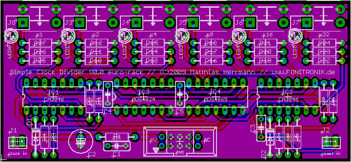
i made a very simple divider these days, using two discrete schmitt triggers, a 4024 and a 4069. by far not that versatile like ken's great Master Divider.
it can be clocked by any signal that is crossing approx. 1.5V. the reset will need a trigger, pulse or square wave though.
it provides the original clock and the divisioons /2, /4, /8, /16 and /32.
i could do a PCB run for these. boards are small and will be cheap. but first i will manufacture a prototype for me anyways, in order to have a regular module.
[EDIT: schematic removed. for updated schematic see below]
comments are appreciated.
_________________

cheers,
matthias
____________
Big Boss at fonitronik
Tech Buddy at Random*Source
Last edited by fonik on Sun Feb 08, 2009 4:26 pm; edited 2 times in total |
|
|
Back to top
|
|
 |
etaoin

Joined: Jun 30, 2005
Posts: 761
Location: Utrecht, NL
|
| Posted: Wed Jan 07, 2009 5:23 am Post subject:
|
|
|
Very creative use of the CA3046. But that will make it relatively "expensive" over just using a bunch of 2N3904 or BC547s, doesn't it?
_________________
http://www.casia.org/modular/ |
|
|
Back to top
|
|
|
fonik
Joined: Jun 07, 2006
Posts: 3950
Location: Germany
Audio files: 23
|
| Posted: Wed Jan 07, 2009 5:53 am Post subject:
|
|
|
| Etaoin wrote: | | Very creative use of the CA3046. But that will make it relatively "expensive" over just using a bunch of 2N3904 or BC547s, doesn't it? |
| Etaoin wrote: | | Very creative use of the CA3046. But that will make it relatively "expensive" over just using a bunch of 2N3904 or BC547s, doesn't it? |

you could use a CA3086 either (differential pair NOT matched). however, i get them for EUR 0.50 each. and it looks so pretty.
i did a 2-sided layout for this circuit. if enough people voted for the use of 2N3904 i could do a 2nd layout. no big deal. this could probably be single-sided for home etching. i will do another layout providing standard connectors instead of cliff sockets anyways.
here is just a screenshot of the PCB layout i want to etch for my eurorack system. the six output sockets (Cliff 1386) will connect the PCB to the front panel:
_________________
cheers,
matthias
____________
Big Boss at fonitronik
Tech Buddy at Random*Source |
|
|
Back to top
|
|
|
etaoin
Joined: Jun 30, 2005
Posts: 761
Location: Utrecht, NL
|
| Posted: Wed Jan 07, 2009 6:05 am Post subject:
|
|
|
| fonik wrote: | | you could use a CA3086 either (differential pair NOT matched). however, i get them for EUR 0.50 each. and it looks so pretty. |
Still, that's a whopping EUR 1 for two ICs, while you get 50 BC547's for EUR 2
CA3046 are more or less EUR 0.50 as well by the way (at Futurlec).
_________________
http://www.casia.org/modular/ |
|
|
Back to top
|
|
|
RF

Joined: Mar 23, 2007
Posts: 1502
Location: Northern Minnesota, USA
Audio files: 28
|
| Posted: Wed Jan 07, 2009 6:11 am Post subject:
|
|
|
I'd be interested in at least 2 of those Matthias - whichever way you go on design.
bruce
_________________
www.sdiy.org/rfeng
"I want to make these sounds that go wooo-wooo-ah-woo-woo.”
(Herb Deutsch to Bob Moog ~1963) |
|
|
Back to top
|
|
|
EdisonRex
Site Admin

Joined: Mar 07, 2007
Posts: 4579
Location: London, UK
Audio files: 172
|
| Posted: Wed Jan 07, 2009 6:27 am Post subject:
|
|
|
Me too, "count" me in for 2. 
_________________
Garret: It's so retro.
EGM: What does retro mean to you?
Parker: Like, old and outdated.
Home,My Studio,and another view |
|
|
Back to top
|
|
|
fonik
Joined: Jun 07, 2006
Posts: 3950
Location: Germany
Audio files: 23
|
| Posted: Wed Jan 07, 2009 8:15 am Post subject:
|
|
|
| Etaoin wrote: | | fonik wrote: | | you could use a CA3086 either (differential pair NOT matched). however, i get them for EUR 0.50 each. and it looks so pretty. |
Still, that's a whopping EUR 1 for two ICs, while you get 50 BC547's for EUR 2
CA3046 are more or less EUR 0.50 as well by the way (at Futurlec). |
you are absolutely right. ICs are 10 transistors/EUR, BC547's 25 transistors/EUR.
however, i am not planning to go to mass production for now , and i must commit that i find it more comfortable to solder a socket than single transistors, but that's just me.
again, i will do a 2nd layout anyways, so...
_________________
cheers,
matthias
____________
Big Boss at fonitronik
Tech Buddy at Random*Source |
|
|
Back to top
|
|
|
Peake

Joined: Jun 29, 2007
Posts: 1113
Location: Loss Angeles
Audio files: 3
|
| Posted: Wed Jan 07, 2009 12:35 pm Post subject:
|
|
|
Have you considered the 4024 clock divider IC? Polyfusion and others used it...and IMO, a couple of un-even divides, such as /3, /5, etc., are very useful..
_________________
We are selling emotions, there are no emotions in a grid. -mwagener
"IC 741. Sometimes you don't want fidelity." -Small Bear Electronics Catalog |
|
|
Back to top
|
|
|
machine.cuisine
Joined: Jul 20, 2007
Posts: 61
Location: ks
Audio files: 4
|
| Posted: Wed Jan 07, 2009 12:44 pm Post subject:
|
|
|
| Since the clock is external, what does 'reset' do? |
|
|
Back to top
|
|
|
kkissinger
Stream Operator

Joined: Mar 28, 2006
Posts: 1452
Location: Kansas City, Mo USA
Audio files: 45
|
| Posted: Wed Jan 07, 2009 12:53 pm Post subject:
You read my mind! |
|
|
I could definitely use a clock divider.
I have been experimenting with my RC50 (loop station) and my Aries Synthesizer.
The RC50 has a MIDI clock output and my Midi-to-CV converter has an option to convert MIDI clock messages to clock pulses. The problem is, the clock messages come in at 24ppq and, in turn, I have to tie up some of my switches to divide the clock pulse to a more useable rate.
I would be interested in a clock divider circuit and if a PCB is available, I would definitely be interested.
By what amount does the circuit divide the clock pulses?
Thank you for posting this.
_________________
-- Kevin
http://kevinkissinger.com |
|
|
Back to top
|
|
|
fonik
Joined: Jun 07, 2006
Posts: 3950
Location: Germany
Audio files: 23
|
| Posted: Wed Jan 07, 2009 2:03 pm Post subject:
|
|
|
| machine.cuisine wrote: | | Since the clock is external, what does 'reset' do? |
the 1st output of the 4024 outputs one pulse per 2 incoming clock pulses, the 2nd ouputs one pulse per 4 incoming clock pulses and so on (i use the divisions /2, /4/, /8, /16 and 32). so you can imagine that some outputs are on and some off after say 20 clock pulses came in. reset just resets the divider IC 4024 and the counting/dividing to its initial status, that is all outputs are on.
@peake: i use just 5 even divisions from the 4024 just because these seemed to be most useful for me. and i wanted to use just 6 inverters (5 for the divisions, one for the original clock) to keep it simple.
i will post a frontpanel sketch tomorrow to make it a little bit more clearer...[EDIT: fpd sketch attached]
| Description: |
|
| Filesize: |
6.26 KB |
| Viewed: |
54624 Time(s) |
|
_________________
cheers,
matthias
____________
Big Boss at fonitronik
Tech Buddy at Random*Source
Last edited by fonik on Wed Jan 07, 2009 4:30 pm; edited 1 time in total |
|
|
Back to top
|
|
|
fonik
Joined: Jun 07, 2006
Posts: 3950
Location: Germany
Audio files: 23
|
|
|
Back to top
|
|
|
fonik
Joined: Jun 07, 2006
Posts: 3950
Location: Germany
Audio files: 23
|
| Posted: Thu Jan 22, 2009 1:46 pm Post subject:
|
|
|
proto PCB arrived today. look nice. BUT: i breadboardrd the circuit using 2n3904 NPNs. for the PCB i used CA3046 or CA3086. they don't work (i tried two different brands).
then i inserted 2N3904 into the IC sockets (what a mess ) and voila, it works.
what could be the cause that the CA3046 won't work?
at the base of the first NPNs of the discrete schmitt triggers i see about 11.5V when using the CA3046 with no clock applied. using 2n3904 i measure 1.15V (which far better ).
what is wrong with using CA3046?
BTW the circuitry of the clock input is wrong. one transistor too much. why? just because the counter counts at each falling edge of the clock  one has to look at the datasheets of the different CMOS very closely. somehow on it felt all well on the breadboard one has to look at the datasheets of the different CMOS very closely. somehow on it felt all well on the breadboard
[EDIT: schematic removed. see updated schematic below]
_________________
cheers,
matthias
____________
Big Boss at fonitronik
Tech Buddy at Random*Source
Last edited by fonik on Sun Feb 08, 2009 4:07 pm; edited 1 time in total |
|
|
Back to top
|
|
|
Adam-V

Joined: Jan 29, 2007
Posts: 300
Location: Australia
Audio files: 1
|
| Posted: Thu Jan 22, 2009 3:12 pm Post subject:
|
|
|
Hi Matthias,
The data sheet for the CA3046 states:
"The collector of each transistor of the CA3046 is isolated from the substrate by an integral diode. The substrate(Terminal 13) must be connected to the most negative point in the external circuit to maintain isolation between transistors and to provide for normal transistor action"
Now I suspect that, since you have used Q5 as a pull-up on one of the outputs, this is causing some issues with the isolation as the substrate is not at the negative most point which for this circuit would be 0V. Try bending Pin 14 out so it's no longer connected to +15V and then ground pin 13 to see if the remainder of the circuit functions correctly. If so, you might need to re work the output stage so that the transistors pull down to ground rather than up to Vcc.
Cheers,
Adam-V
_________________
Digitalis Effect | Fractured Symmetry (www.spiralsect.com) |
|
|
Back to top
|
|
|
fonik
Joined: Jun 07, 2006
Posts: 3950
Location: Germany
Audio files: 23
|
|
|
Back to top
|
|
|
fonik
Joined: Jun 07, 2006
Posts: 3950
Location: Germany
Audio files: 23
|
| Posted: Sun Feb 08, 2009 4:17 pm Post subject:
|
|
|
below you see pictures of my finished divider module.
as you will recognize, i used inverters. why? this way all divisions are "ON" when reset pulse is received.
i never have had a divider before, and for me it has been just natural to have it this way. i looked about it as it would be a sequencer: i.e. the Klee2 reloads on the pulse and is at the "one" of the pattern when reload (reset) pulse is received. i would think a divider should operate the same way, when it gets controlled by another divider or sequencer or whatever. am i wrong here? woult it be better to have all divisions "OFF" when reset is received? then the reset pulse would have to be the last step in a sequence!?
any opinion would be appreciated...


_________________
cheers,
matthias
____________
Big Boss at fonitronik
Tech Buddy at Random*Source |
|
|
Back to top
|
|
|
kkissinger
Stream Operator
Joined: Mar 28, 2006
Posts: 1452
Location: Kansas City, Mo USA
Audio files: 45
|
| Posted: Sun Feb 08, 2009 5:50 pm Post subject:
beautiful work |
|
|
Just beautiful. Hat's off to you.
_________________
-- Kevin
http://kevinkissinger.com |
|
|
Back to top
|
|
|
Adam-V
Joined: Jan 29, 2007
Posts: 300
Location: Australia
Audio files: 1
|
| Posted: Sun Feb 08, 2009 9:29 pm Post subject:
|
|
|
Nice work Matthias. I think your logic is correct and makes for a musically useful divider, at least as far as clocks are concerned, as it places the positive edges of the divided outputs on the 1, 2, 4, 8 etc beats.
I reckon you could have achieved the same result by using a down counter without inverting the outputs.
Cheers,
Adam-V
_________________
Digitalis Effect | Fractured Symmetry (www.spiralsect.com) |
|
|
Back to top
|
|
|
sduck

Joined: Dec 16, 2007
Posts: 459
Location: Nashville
Audio files: 5
|
| Posted: Sun Feb 08, 2009 9:53 pm Post subject:
|
|
|
| This is great, and just the kind of thing I think would work great with my klee - let us know when and if you have pcb's available, I'll take 2! |
|
|
Back to top
|
|
|
cthulu

Joined: Feb 07, 2009
Posts: 56
Location: Göteborg, Sweden
|
| Posted: Mon Feb 09, 2009 2:20 am Post subject:
|
|
|
Beautiful job!
To me the step from a working schematic to a final module is a huge one.  PCB and frontplate working PCB and frontplate working
together... yuck! I'll look around in here for some clues though 
I think the trannies on the output are a bit redundant. Since you have the inverters I think you could just let
the divider sink the LED's and eventually just increase the output resistors. if Q1 can't pull the clock pin
low and sink an LED at the same time yould have to buffer it ( keep that one as it is... ). I don't know about inverting
the outputs or not, I just divide and conquer and haven't actually thought about it until I read this post...
Oskar |
|
|
Back to top
|
|
|
fonik
Joined: Jun 07, 2006
Posts: 3950
Location: Germany
Audio files: 23
|
| Posted: Mon Feb 09, 2009 3:06 am Post subject:
|
|
|
| cthulu wrote: | I think the trannies on the output are a bit redundant. Since you have the inverters I think you could just let
the divider sink the LED's and eventually just increase the output resistors. if Q1 can't pull the clock pin
low and sink an LED at the same time yould have to buffer it ( keep that one as it is... ). |
 she blinded me with science... she blinded me with science...
it could have been be so easy? however, now as you pointed it out i get aware that these transistors are just relicts from the first breadboarding without inverters 
_________________
cheers,
matthias
____________
Big Boss at fonitronik
Tech Buddy at Random*Source |
|
|
Back to top
|
|
|
Funky40
Joined: Sep 24, 2005
Posts: 875
Location: Swiss
Audio files: 1
G2 patch files: 5
|
| Posted: Mon Feb 09, 2009 1:31 pm Post subject:
|
|
|
very nice work Matthias !
i have sometimes troubles with my doepfer divider A-160 +161 when i feed lots of destinations and when i like to run up to high audiospeeds.
maybe its not stuppid to have the transistors. ( but i don't understand any electronics  ) ) |
|
|
Back to top
|
|
|
Adam-V
Joined: Jan 29, 2007
Posts: 300
Location: Australia
Audio files: 1
|
| Posted: Mon Feb 09, 2009 2:52 pm Post subject:
|
|
|
I agree, the transistor drivers on the outputs are a good thing.
Cheers,
Adam-V
_________________
Digitalis Effect | Fractured Symmetry (www.spiralsect.com) |
|
|
Back to top
|
|
|
fonik
Joined: Jun 07, 2006
Posts: 3950
Location: Germany
Audio files: 23
|
| Posted: Mon Feb 09, 2009 3:19 pm Post subject:
|
|
|
i couldn't find any max current rating for the outputs on the datasheet. maybe i am just dumb...
_________________
cheers,
matthias
____________
Big Boss at fonitronik
Tech Buddy at Random*Source |
|
|
Back to top
|
|
|
blue hell
Site Admin

Joined: Apr 03, 2004
Posts: 24493
Location: The Netherlands, Enschede
Audio files: 298
G2 patch files: 320
|
| Posted: Mon Feb 09, 2009 3:52 pm Post subject:
|
|
|
| fonik wrote: | | maybe i am just dumb... |
Maybe not ... sometimes that kind of data is in a family data sheet for a whole logic family and not in the individual ones ...
_________________
Jan
also .. could someone please turn down the thermostat a bit.
 |
|
|
Back to top
|
|
|
|

 Forum index » DIY Hardware and Software » fonik's place