| Author |
Message |
6581r4AR

Joined: Apr 03, 2011
Posts: 15
Location: Texas, USA
|
|
|
Back to top
|
|
 |
Kabzoer

Joined: Feb 07, 2011
Posts: 82
Location: Belgium
|
 Posted: Thu Apr 07, 2011 12:19 pm Post subject: Posted: Thu Apr 07, 2011 12:19 pm Post subject:
|
  |
|
| I don't think it will make any difference. |
|
|
Back to top
|
|
|
tjookum

Joined: May 25, 2010
Posts: 360
Location: Netherlands
Audio files: 26
|
| Posted: Sat Apr 09, 2011 3:39 am Post subject:
|
|
|
I don't think I've ever seen the right one but Im very sure the left one works without changing the frequency.
This, for me, is the best part about lunetta's, it's just 5 min on the breadboard and you have your answer. Just experiment and have fun!
_________________
There he goes. One of God's own prototypes. A high-powered mutant of some kind never even considered for mass production. Too weird to live, and too rare to die.
Hunter S. Thompson
movies
noise |
|
|
Back to top
|
|
|
6581r4AR
Joined: Apr 03, 2011
Posts: 15
Location: Texas, USA
|
| Posted: Sat Apr 09, 2011 6:32 am Post subject:
|
|
|
| tjookum wrote: |
This, for me, is the best part about lunetta's, it's just 5 min on the breadboard and you have your answer. Just experiment and have fun! |
Yes, like I said I don't have the parts yet to experiment. I have yet to get a hearty supply of useful broken electronics to pull from... I'm fairly new to building and designing. I really appreciate the help. |
|
|
Back to top
|
|
|
richardc64

Joined: Jun 01, 2006
Posts: 679
Location: NYC
Audio files: 26
|
| Posted: Sat Apr 09, 2011 8:46 am Post subject:
|
|
|
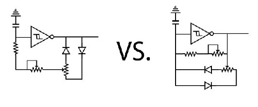
I can't even begin to figure how the right circuit behaves. It looks as if the location of the freq. pot pretty much defeats what the width pot is supposed to do.
In the circuit on the left, the width pot won't affect the frequency, but each pot's value will affect the range of effect obtainable from the other. Consider if both pots are 100k and the fixed resistor is 1k. The setting of the width pot doesn't matter. Whether it's set for 1k half a cycle and 99k the other half, or 37k/63k, the total average value with respect to the timing is 50k. If the 100k freq pot is set for zero ohms the value R in the equation f=1/RC (which is only approximate for these oscillators,) is 51k, and the pulse width can be varied from roughly 2% to 98%. If the freq pot is set to 100k the total R is 151k: only 3 times what it was with the pot at 0. The freq range is only 1:3 Furthermore, the the pulse width range is reduced by 1/3rd (I think,) because the 50k average value becomes a smaller percentage of the total R.
Attempting to get a wider frequency range by increasing the value of the freq pot just makes matters worse, width-wise. Increase the width pot's value, and frequency range will again be diminished. The trick will be finding an acceptable compromise of freq range vs width range.
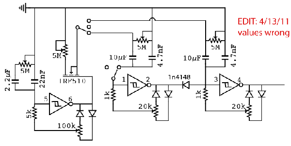
One possible solution may be to control the frequency not by varying R, but by varying C. This can be done with a multi-position switch, which is too crude to even consider, or smoothly, with a pot. In the sample below, you hear the frequency go from LFO range up into audio. In the schematic showing the values I used, greater resistance = higher frequency. Note that the "controlled" capacitor is 10x the value of the uncontrolled one. Other ratios are probably feasible. I did not try width control.
(Affect/Effect)
| Description: |
| C can also be voltage controlled |
|
| Filesize: |
4.59 KB |
| Viewed: |
14964 Time(s) |

|
| Description: |
|

Download |
| Filename: |
vary_c.mp3 |
| Filesize: |
528.98 KB |
| Downloaded: |
1175 Time(s) |
_________________
Revenge is a dish best served with a fork... to the eye |
|
|
Back to top
|
|
|
6581r4AR
Joined: Apr 03, 2011
Posts: 15
Location: Texas, USA
|
|
|
Back to top
|
|
|
richardc64
Joined: Jun 01, 2006
Posts: 679
Location: NYC
Audio files: 26
|
| Posted: Sun Apr 10, 2011 12:57 am Post subject:
|
|
|
| 6581r4AR wrote: | | So you're saying something like this would be more appropriate? or does that put me right where I started? |
Looks good to me. I omitted the width control in my schematic because I hadn't tried it. I was concentrating on a method of frequency control that should be immune to width variations.
| Quote: | | And why is that feedback resistor(470K) so high? Is it just setting the highest frequency reachable? |
I already had a 40106 oscillator on breadboard, and I plugged in parts that were at hand to get a range of frequencies that could be heard as slow clicks up into audio. But I see now that, using the reasoning in my first post, to get 10/90% pulse width the width pot needs to be 20 times the fixed resistor, which in my example would be 10Meg! Ridiculous! 
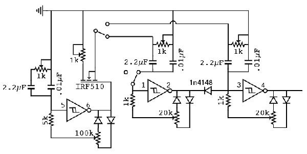
Scaling by a factor of 10, 47k would need a 1M pot to get roughly 10-90% width control and caps 10x larger -- 0.1 and 1uF to get the same frequencies.
| Quote: | | And just so I understand correctly, in my original post, the one on the left will work except the larger the freq resistance is the less width range will work? |
Correct. 'Way to cut through the verbosity, guy 
_________________
Revenge is a dish best served with a fork... to the eye |
|
|
Back to top
|
|
|
6581r4AR
Joined: Apr 03, 2011
Posts: 15
Location: Texas, USA
|
|
|
Back to top
|
|
|
richardc64
Joined: Jun 01, 2006
Posts: 679
Location: NYC
Audio files: 26
|
| Posted: Sun Apr 10, 2011 4:52 am Post subject:
|
|
|
| 6581r4AR wrote: | | richardc64 wrote: |
Scaling by a factor of 10, 47k would need a 1M pot to get roughly 10-90% width control and caps 10x larger -- 0.1 and 1uF to get the same frequencies.
|
How would I calculate the width percent like you did? |
Because of the diodes, the width pot's contribution to the frequency can be only half its total amount, no matter where it's set. 47k is slightly less than 10% of 1M/2, so fully clockwise or counter-clockwise the width will be 10% one part of a cycle and 90% for the remainder.
| Quote: | | I think I understand the ƒ=1/RC equation... |
Vcc plays a part in calculating the frequency of schmitt trigger oscillators. I've ignored that and haven't calculated anything: I've guesstimated. I start with common parts values, then increase or decrease until a circuit sounds like what I wanted.
| Quote: | | Attached is what I'm trying to work on so you get a better idea of my intentions. Any values jump out as ridiculous or unnecessary? Should pots be linear or log? |
I don't understand what the fet is supposed to do. The width pots should be linear. For freq, I don't think it matters too much.
I only tried 1M for that freq control method. I don't know if more than that would be useful or usable. 5M is impractical for two reasons. First, for some unknown reason high-value pots are getting harder to find. Even 1M is not as common as it used to be. Secondly, tuning will be extremely coarse, especially with the unrealistic range you stated.
| Quote: | | Thats why I would like as many useful equations or methods to help me get as close as possible on paper before I tweek the rest on the breadboard.. Also so I don't have to bug someone else for work I should be doing and learning for myself. |
Heh. A few people here have been known to get a bit testy, at times, but no one's gonna get seriously "bugged." But it bears repeating:
| tjookum wrote: | | This, for me, is the best part about lunetta's, it's just 5 min on the breadboard and you have your answer. Just experiment and have fun! |
it's/its
_________________
Revenge is a dish best served with a fork... to the eye |
|
|
Back to top
|
|
|
6581r4AR
Joined: Apr 03, 2011
Posts: 15
Location: Texas, USA
|
| Posted: Sun Apr 10, 2011 5:11 am Post subject:
|
|
|
The mosfet is 'sposed to be a switch controlled by the LFO, modulating frequency of either the main osc or the synced osc. It turns on and off the extra pot reducing the resistance of the one it is attached to. Is that wrong too? I just followed the example of the "How to make a digital synth" on the hackaday page.
Other than that, I think I understand everything a little better now. Thanks so much for the help. *big smile* |
|
|
Back to top
|
|
|
richardc64
Joined: Jun 01, 2006
Posts: 679
Location: NYC
Audio files: 26
|
| Posted: Mon Apr 11, 2011 5:48 am Post subject:
|
|
|
I found another reason not use too high a value for the feedback resistor: it affects the duty-cycle regardless of any width control that may be present.
As can be seen in the screen captures, at 100k the waveform is fairly close to being 50-50, but at 330k the asymmetry becomes more significant. With 1M (and a smaller cap to keep the freq reasonable,) the shape is most definitely non-square.
This is something the schmitt trigger datasheets don't mention. (Edit: Or maybe they do -- somewhere in the equation.)
There's probably some highly technical explanation for this, and the slope of the "1" state might offer a clue. But the effect is of little concern when the oscillator is an audio source -- especially in Lunetta's, which are supposed to be "dirty." As modulation or gating, though, the asymmetry could be noticeable and undesireable. It might cause glitches when clocking sequencers and latches, and is an added complication when attempting to control the pulse width.
| Description: |
| If I knew how to inset this as text, I would have. And WTF is that lower-case script "L"? |
|
| Filesize: |
5.39 KB |
| Viewed: |
14797 Time(s) |
|
| Description: |
| Recordings made in Wavosaur |
|
| Filesize: |
13.53 KB |
| Viewed: |
470 Time(s) |
| This image has been reduced to fit the page. Click on it to enlarge. |
|
_________________
Revenge is a dish best served with a fork... to the eye |
|
|
Back to top
|
|
|
6581r4AR
Joined: Apr 03, 2011
Posts: 15
Location: Texas, USA
|
| Posted: Mon Apr 11, 2011 12:45 pm Post subject:
|
|
|
WOW. That's super helpful... Now if I only knew what those variables represented. =P I'll do some searching into it.
And I went out and got myself a 40106 the other day so I could do some testing for myself. I found that replacing the not so reasonable 5M idea with a 1K did well. I found that over a certain threshold, it just cut off the control cap all together. The key is finding that threshold point and making the variable resistor as small as possible for a smooth freq sweep. |
|
|
Back to top
|
|
|
6581r4AR
Joined: Apr 03, 2011
Posts: 15
Location: Texas, USA
|
|
|
Back to top
|
|
|
|

 Forum index » DIY Hardware and Software » Lunettas - circuits inspired by Stanley Lunetta