| Author |
Message |
fvsr
Joined: Mar 05, 2014
Posts: 7
Location: Brazil
|
 Posted: Fri Jan 08, 2016 8:17 pm Post subject:
The Circular Clock Divider Posted: Fri Jan 08, 2016 8:17 pm Post subject:
The Circular Clock Divider
Subject description: a DIY open source PIC based electronic project |
  |
|
Hi
The Circular Clock Divider is a simple projet which I made the hardware and firmware from scratch, inspired from other projects that are alredy in the market. Its an open source PIC based electronic project which you can, with some basic skills in electronics, build, use and modify at will.
If you want to produce polyrythms and interesting rythmic constructions, you may look at this project, since it can, using a single stream of pulses, produce eight different output frequencies of pulses, based in eight different dividers, plus the clock output, and you can change the dividers all the time.
The schematic:
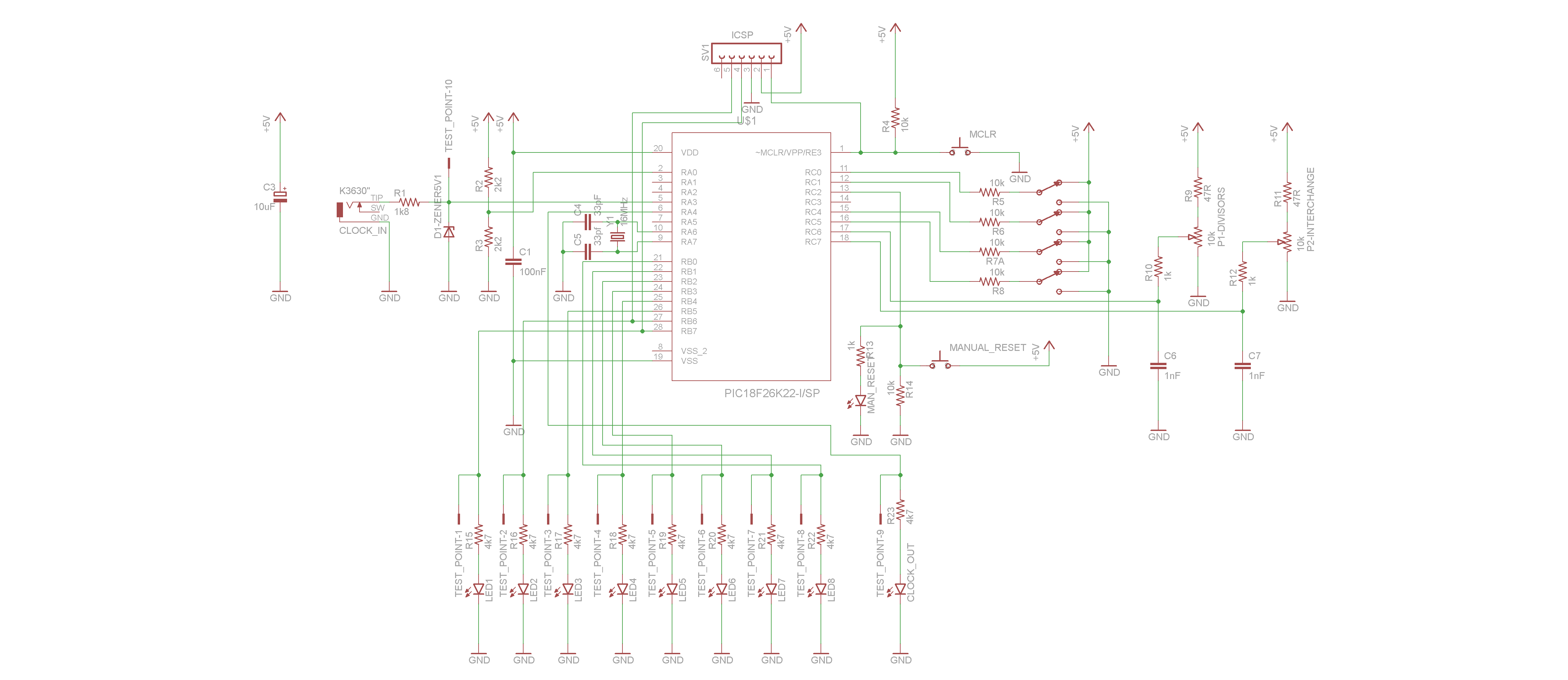
Features:300us response delay, up to 2KHz working frequency, 8 different output frequencies all the time, 256 interchangeable dividers arrays, trigger/gate, up beat/down beat, spread, auto-reset and manual reset modes.
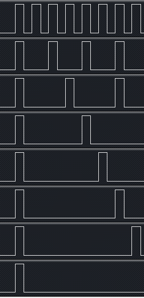
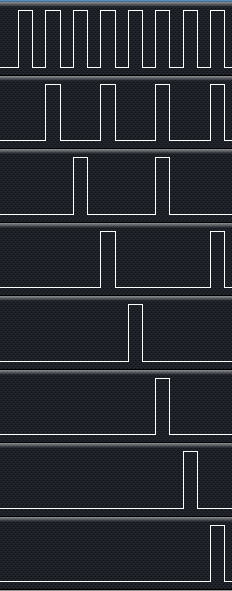
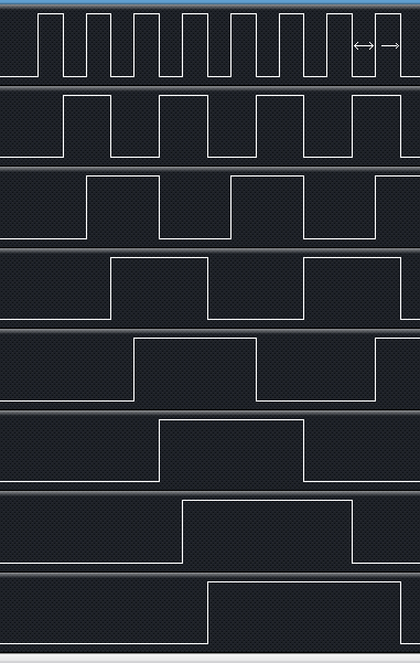
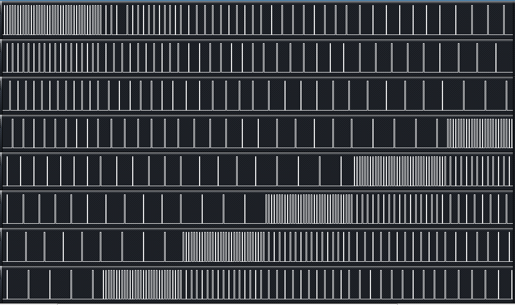
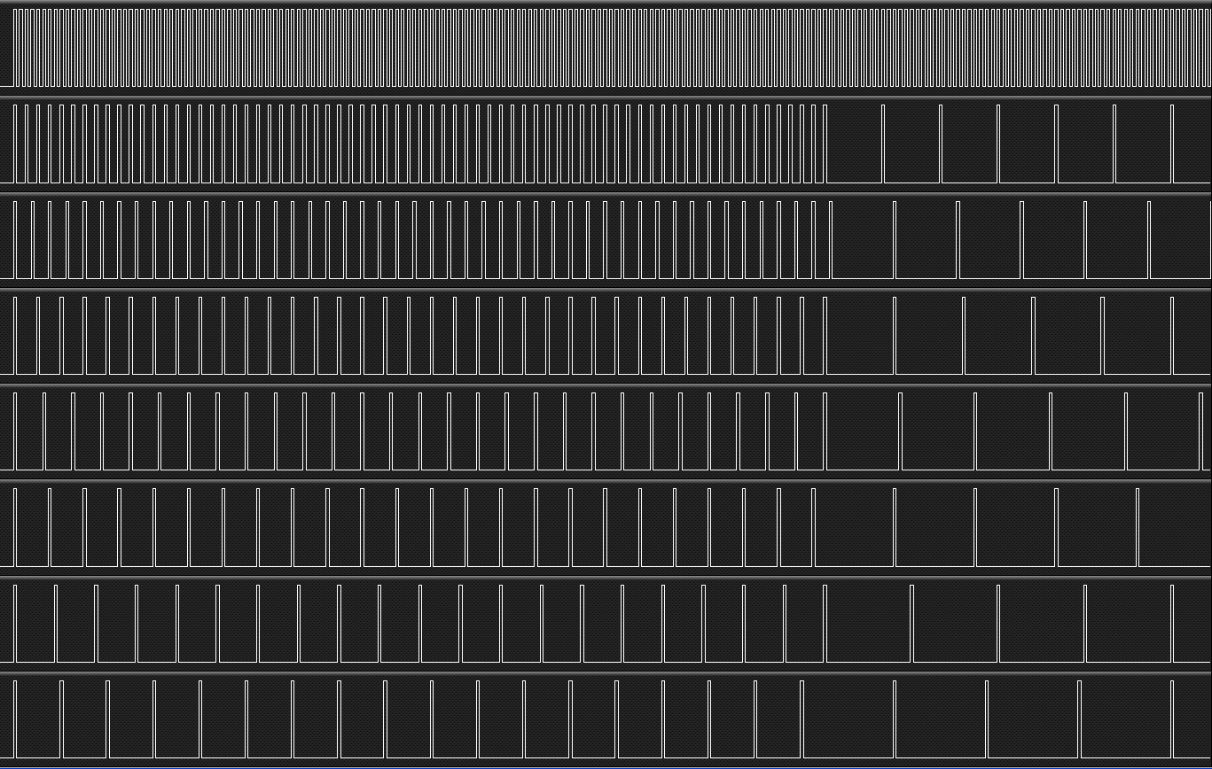
Some of signals that the Circular Clock Divider can generate, captured by a logic analyzer:
Trigger and down beat modes:
Trigger and up beat modes:
Gate and down beat modes

Gate and up beat modes
Trigger and down beat modes are selected, circulate potentiometer is turned right to increase the voltage. The divisors potentiometer was allways at 0V. The divisors array changed from {1,2,3,4,5,6,7,8}, to {2,3,4,5,6,7,8,1}, {3,4,5,6,7,8,1,2}, {4,5,6,7,8,1,2,3}, {5,6,7,8,1,2,3,4}, {6,7,8,1,2,3,4,5}, {7,8,1,2,3,4,5,6}, {8,1,2,3,4,5,6,7}.
Trigger and down beat modes are selected, divisors potentiometer is turned right to increase the voltage. The divisors array changed from {1,2,3,4,5,6,7,8} to {9,10,11,12,13,14,15,16}, after a reset. The circulate potentiometer was allways at 0V. The first track is the clock output (comparator output) in order to maintain a reference.
The link to the Word Press blog is here:
https://mcuprojectsblog.wordpress.com/2015/12/27/the-circular-clock-divider-v-1/
I think the project is well documented, but let me know if someone needs more information. I will adapt the code for at least three different microcontroller models, so the part will not be a problem. I hope someone get encouraged to build the prototype and live a coment.
Best regards.[/img]
Last edited by fvsr on Tue Jan 19, 2016 1:50 am; edited 2 times in total |
|
|
Back to top
|
|
 |
LFLab
Joined: Dec 17, 2009
Posts: 497
Location: Rosmalen, Netherlands
|
 Posted: Sat Jan 09, 2016 1:37 pm Post subject: Posted: Sat Jan 09, 2016 1:37 pm Post subject:
|
  |
|
| Interesting! I was planning on doing something similar in Arduino, will look into your project for clues! |
|
|
Back to top
|
|
 |
fvsr
Joined: Mar 05, 2014
Posts: 7
Location: Brazil
|
 Posted: Sat Jan 09, 2016 2:09 pm Post subject: Posted: Sat Jan 09, 2016 2:09 pm Post subject:
|
  |
|
| LFLab wrote: | | Interesting! I was planning on doing something similar in Arduino, will look into your project for clues! |
Hi, I'm glad you found it interesting, be my guest to use any information at the blog. It would be nice if you could post some of your results here. |
|
|
Back to top
|
|
 |
1_over_f_noise
Joined: Mar 14, 2010
Posts: 10
Location: Italy
|
 Posted: Thu Jan 14, 2016 11:18 am Post subject: Posted: Thu Jan 14, 2016 11:18 am Post subject:
|
  |
|
Hi fvsr,
very interesting device!
I would like try it in the easy way, but when I go on your blog and I try to download the .hex version, my browser don't allow me of doing it caused by an security warning.
What I have mistaken? |
|
|
Back to top
|
|
 |
fvsr
Joined: Mar 05, 2014
Posts: 7
Location: Brazil
|
 Posted: Fri Jan 15, 2016 6:02 am Post subject: Posted: Fri Jan 15, 2016 6:02 am Post subject:
|
  |
|
| 1_over_f_noise wrote: | but when I go on your blog and I try to download the .hex version, my browser don't allow me of doing it caused by an security warning.
What I have mistaken? |
Sorry about that, and thanks for the warning.
I have changed all links at the blog to Google Drive sharing links, and I think the problem is solved now. If you have any other problems let me know.
If you could post your results here it would be nice. |
|
|
Back to top
|
|
 |
dougseidel

Joined: Feb 10, 2010
Posts: 74
Location: NJ
|
|
|
Back to top
|
|
 |
1_over_f_noise
Joined: Mar 14, 2010
Posts: 10
Location: Italy
|
 Posted: Sun Jan 17, 2016 5:13 am Post subject: Posted: Sun Jan 17, 2016 5:13 am Post subject:
|
  |
|
Hi there!
Thank you for your very kind and fast answer!
Problem fixed!
I succesfully downloaded your file .hex!
I'll try to use the MikroProg Programmer (by MikroE) in order to upload it on the PIC (that I have to buy...).
As soon as possible, I'll try to put on breadboard your extremely interesting project and of course I'll post every result! |
|
|
Back to top
|
|
 |
fvsr
Joined: Mar 05, 2014
Posts: 7
Location: Brazil
|
 Posted: Sun Jan 17, 2016 12:03 pm Post subject: Posted: Sun Jan 17, 2016 12:03 pm Post subject:
|
  |
|
| 1_over_f_noise wrote: |
Problem fixed!
I succesfully downloaded your file .hex! |
I'm glad that the problem is solved! I think Goggle provides a stable service.
| 1_over_f_noise wrote: |
I'll try to use the MikroProg Programmer (by MikroE) in order to upload it on the PIC |
I think MikroProg Programmer is a good choice. I have EasyPIC v7, and it is so well made, works very well. It must be better than Microchip's PICkit 3 (the little red), which is a big problem, mostly because its software is crap.
At the MikroProg's page you can see a list of supported devices, and PIC18F26K22 is there.
Remember that the crystal's frequency must be 16MHz or lower, to get 64MHz (in x4 PLL mode), the maximum operating frequency for PIC18F26K22.
| 1_over_f_noise wrote: |
(that I have to buy...) |
I'm reviewing the code for PIC18F2520, with wich I have already running this project, and soon I will post it. I think that PIC18F4520 must be easier to find.
| 1_over_f_noise wrote: |
As soon as possible, I'll try to put on breadboard your extremely interesting project and of course I'll post every result! |
I am looking forward to see your results, good luck! |
|
|
Back to top
|
|
 |
1_over_f_noise
Joined: Mar 14, 2010
Posts: 10
Location: Italy
|
 Posted: Tue Jan 19, 2016 9:49 am Post subject: Posted: Tue Jan 19, 2016 9:49 am Post subject:
|
  |
|
| Quote: | I think MikroProg Programmer is a good choice. I have EasyPIC v7, and it is so well made, works very well. It must be better than Microchip's PICkit 3 (the little red), which is a big problem, mostly because its software is crap.
At the MikroProg's page you can see a list of supported devices, and PIC18F26K22 is there.
Remember that the crystal's frequency must be 16MHz or lower, to get 64MHz (in x4 PLL mode), the maximum operating frequency for PIC18F26K22. |
Thanks vey much for the hints, I'm on my way to order the PIC18F26K22!
| Quote: |
I am looking forward to see your results, good luck!
|
Thanks... When ready, I'll try to regularly post every step concerning your project in order to share technical and musical results!  |
|
|
Back to top
|
|
 |
fvsr
Joined: Mar 05, 2014
Posts: 7
Location: Brazil
|
|
|
Back to top
|
|
 |
Paradigm X
Joined: Feb 15, 2011
Posts: 363
Location: Null and void
Audio files: 2
|
 Posted: Mon Feb 01, 2016 9:51 am Post subject: Posted: Mon Feb 01, 2016 9:51 am Post subject:
|
  |
|
hey this is perfect, just what i was looking for. I even have the correct pIC chip!
Great project!
Are you planning on making any PCBs for this?
Many thanks, BEn |
|
|
Back to top
|
|
 |
fvsr
Joined: Mar 05, 2014
Posts: 7
Location: Brazil
|
 Posted: Mon Feb 01, 2016 5:32 pm Post subject: Posted: Mon Feb 01, 2016 5:32 pm Post subject:
|
  |
|
| Paradigm X wrote: | | hey this is perfect, just what i was looking for. I even have the correct pIC chip! |
Hi! I`m glad you liked it.
One of the guidelines of this project is that it must have features of another project already in production. And it ended up being "migratable" to other 28 pins MCUs. Maybe I'll write code for PIC18F2550, which I think is also very easy to obtain.
| Paradigm X wrote: | | Great project! |
Thanks. I hope you can build it with almost no difficulties. In case you manage to build it, it'd be awesome if could post some results or reviews.
| Paradigm X wrote: | | Are you planning on making any PCBs for this? |
For now I`m waiting the project to mature itself through possible future community contributions, and/or other code revisions and/or migrations. Some change in the hardware may be necessary.
| Paradigm X wrote: | | Many thanks, BEn |
Enjoy! |
|
|
Back to top
|
|
 |
Paradigm X
Joined: Feb 15, 2011
Posts: 363
Location: Null and void
Audio files: 2
|
 Posted: Tue Feb 02, 2016 2:54 am Post subject: Posted: Tue Feb 02, 2016 2:54 am Post subject:
|
  |
|
Hi
Im not very good at stripboard layouts etc unfortunately, although i might give it a go.
If i do i will certainly post here.
For the price of ten pcbs from itead or seeed i might suggest its worth getting some pcbs done now, and maybe more another time? I paid like £10 for 10 pcbs, including shipping. I would be happy to pay for a run and send you them if youre interested?
Was funny, ive been trying to work out how best to do the 'down beat' mode for a while, and youve cracked it!
Cheers
Ben |
|
|
Back to top
|
|
 |
fvsr
Joined: Mar 05, 2014
Posts: 7
Location: Brazil
|
 Posted: Tue Feb 02, 2016 5:24 am Post subject: Posted: Tue Feb 02, 2016 5:24 am Post subject:
|
  |
|
| Paradigm X wrote: |
Was funny, ive been trying to work out how best to do the 'down beat' mode for a while, and youve cracked it! |
It's like this:
The remain equation is z = x % y.
For example, if x=7 and y=3, then 7/3=2 and z=1, the remain is 1.
If x>y, then z = remain;
If x=y, or x is multiple of y, z must be 0;
If x is less than y, then z=x;
If x=0 and y>0, then x<y, then z=x=0, for any given y.
At the first beat all counters are = 1. If I do like this
x = (counter - 1) % divisor
x will be zero for all counters, then z will be 0 for any given divisor,
voilà, down beat!
| Paradigm X wrote: | | For the price of ten pcbs from itead or seeed i might suggest its worth getting some pcbs done now, and maybe more another time? I paid like £10 for 10 pcbs, including shipping. I would be happy to pay for a run and send you them if youre interested? |
I didn't even begin to make the Eagle project, but thanks anyway, maybe latter?
Last edited by fvsr on Wed Feb 03, 2016 5:23 am; edited 3 times in total |
|
|
Back to top
|
|
 |
Paradigm X
Joined: Feb 15, 2011
Posts: 363
Location: Null and void
Audio files: 2
|
 Posted: Tue Feb 02, 2016 5:43 am Post subject: Posted: Tue Feb 02, 2016 5:43 am Post subject:
|
  |
|
Voila indeed!
Cool - sorry, i had assumed it was ready to go as you'd done the schematic.
Sorry, not trying to rush you 
I might have a go at breadboarding/stripboarding it.
Many thanks
Ben |
|
|
Back to top
|
|
 |
|

