| Author |
Message |
MrZu
Joined: Mar 23, 2017
Posts: 10
Location: Taiga
|
 Posted: Thu Mar 23, 2017 7:47 pm Post subject:
Thomas Henry LM VCO problem Posted: Thu Mar 23, 2017 7:47 pm Post subject:
Thomas Henry LM VCO problem
Subject description: It won't work, just silence. Has a voice when touching pins 5 and 7 of the LM13700 |
  |
|
Hi everyone!
Has anyone any experience with the Thomas Henry LM VCO?
I breadboarded one after purchasing a copy of An Analogue Synthesizer for the 21st Century.
I double checked all soldering connections, ground and power as well. Everything seems proper. But it won't work, just silence. 
I couldn’t find LF444, so I replaced it with TL074, I also used 2N5457 instead of the MPF102. Maybe the LF444 and MPF102 is critical for the layout?
I also noticed that if I touch pins 5 and 7 of the LM13700 I can hear a signal out - for sine out is a sine, for ramp out is a ramp … etc… Fine and Coarse control pots do nothing.
Is anyone familiar with this, or has any idea why I'm getting these results?
Thanks in advance! |
|
|
Back to top
|
|
 |
elmegil

Joined: Mar 20, 2012
Posts: 2177
Location: Chicago
Audio files: 16
|
| Posted: Thu Mar 23, 2017 10:13 pm Post subject:
|
|
|
What's your C3?
Polystyrenes are VERY easy to melt. Sounds vaguely like you have no (or insufficient) capacitance until you add your own with your fingers.
Edit:
As for the pots, see whether you get any voltage change at IC2a pin1 when you adjust those pots. If not, you may have a hook-up problem. If you do, perhaps the problem is the 2SA798. Those are fairly rare, you may have gotten a bogus one? |
|
|
Back to top
|
|
|
MrZu
Joined: Mar 23, 2017
Posts: 10
Location: Taiga
|
| Posted: Fri Mar 24, 2017 2:25 am Post subject:
|
|
|
Hi!
| elmegil wrote: | | What's your C3? |
I use ceramic capacitors. Hope it is not critical. 
| elmegil wrote: | | As for the pots, see whether you get any voltage change at IC2a pin1 when you adjust those pots. If not, you may have a hook-up problem. If you do, perhaps the problem is the 2SA798. Those are fairly rare, you may have gotten a bogus one? |
I'm not quite sure I make the measurements right , but the voltage across the pot (from the middle pin) and pin 1 of IC2a is shifting when I adjust the pots.
So maybe I've got a bogus one. And that's a pity, because it is not easy to get!
Is there a replacement for 2SA798? |
|
|
Back to top
|
|
|
elmegil
Joined: Mar 20, 2012
Posts: 2177
Location: Chicago
Audio files: 16
|
| Posted: Fri Mar 24, 2017 5:08 am Post subject:
|
|
|
Ceramic caps can be ok, but you need good quality and stability there, so a C0G type. Classic "disc" type ceramic caps wouldn't be a good choice.
You should measure from ground to pin 1.
A matched pair of PNP transistors would work in place of the 2SA798. Hand matched or something like the SSM2220. |
|
|
Back to top
|
|
|
MrZu
Joined: Mar 23, 2017
Posts: 10
Location: Taiga
|
| Posted: Fri Mar 24, 2017 5:26 am Post subject:
|
|
|
| elmegil wrote: | | You should measure from ground to pin 1 |
So, the voltage at the pin 1 of IC2a is 11.5V and no change while adjusting the pots. It is about 10V at pin2 (unchangeable). And again checked all connections, and it's ok. No hook-up problem found.  |
|
|
Back to top
|
|
|
elmegil
Joined: Mar 20, 2012
Posts: 2177
Location: Chicago
Audio files: 16
|
| Posted: Fri Mar 24, 2017 8:13 am Post subject:
|
|
|
What's your supply voltage?
If I assume 12V, then that sounds like the op amp is stuck at the + rail.
It also sounds like the wiper voltage is changing? (measure before R34/R52, not after, the other side is supposed to be a virtual ground courtesy of the op amp, so you'll see no voltage change there).
That really sounds like something wrong with the op amp itself if your wiring/soldering is ok. In this particular case I would not consider the LF444 to be critical, a TL074 should work just fine.
Are you sure the tempco is in correctly? I could see a problem with your feedback there leading to this kind of thing possibly.
Edit: and don't worry if you don't have a tempco, or don't have another to try. A regular resistor there should work too, it's just that you won't have temp stability. |
|
|
Back to top
|
|
|
MrZu
Joined: Mar 23, 2017
Posts: 10
Location: Taiga
|
| Posted: Fri Mar 24, 2017 8:59 am Post subject:
|
|
|
| elmegil wrote: | | What's your supply voltage? If I assume 12V, then that sounds like the op amp is stuck at the + rail. |
Actually, it is 15V  I use MFOS PSU. I use MFOS PSU.
So voltage across pins 4 and 11 of IC2 is about 14,5V. I noticed that if PSU doesn't supply the VCO the voltage from PSU is about 14,9V
| elmegil wrote: | | It also sounds like the wiper voltage is changing? (measure before R34/R52, not after, the other side is supposed to be a virtual ground courtesy of the op amp, so you'll see no voltage change there). |
The voltage at R34/R52 is changing by those pots. But after is always 11.5V
| elmegil wrote: | Are you sure the tempco is in correctly? I could see a problem with your feedback there leading to this kind of thing possibly.
Edit: and don't worry if you don't have a tempco, or don't have another to try. A regular resistor there should work too, it's just that you won't have temp stability. |
I don't have tempo  I use 2K resistor instead of it. Temp stability is not the main problem I use 2K resistor instead of it. Temp stability is not the main problem  |
|
|
Back to top
|
|
|
elmegil
Joined: Mar 20, 2012
Posts: 2177
Location: Chicago
Audio files: 16
|
| Posted: Fri Mar 24, 2017 9:37 am Post subject:
|
|
|
| MrZu wrote: | | elmegil wrote: | | What's your supply voltage? If I assume 12V, then that sounds like the op amp is stuck at the + rail. |
Actually, it is 15V I use MFOS PSU.
So voltage across pins 4 and 11 of IC2 is about 14,5V. I noticed that if PSU doesn't supply the VCO the voltage from PSU is about 14,9V
|
That sounds like something is wrong and pulling too much current.
| MrZu wrote: | | elmegil wrote: | | It also sounds like the wiper voltage is changing? (measure before R34/R52, not after, the other side is supposed to be a virtual ground courtesy of the op amp, so you'll see no voltage change there). |
The voltage at R34/R52 is changing by those pots. But after is always 11.5V |
So your problem is somewhere between the pots and that op amp, or the op amp itself. I'd try swapping it for another. |
|
|
Back to top
|
|
|
MrZu
Joined: Mar 23, 2017
Posts: 10
Location: Taiga
|
Posted: Fri Mar 24, 2017 9:08 pm Post subject:
 |
|
|
| elmegil wrote: | | That sounds like something is wrong and pulling too much current. |
I think so. I try to measure without ICs in the sockets - and it is 14.5V across pins 4 and 11, the same. And try to measure without 2SA798 and then without Q5. Nothing changes.
Without supplying the VCO the voltage from PSU is about 14,9V (across + / - and +/0), but if it supplies the VCO the voltage across +/- is about 14,5 and across +/0 is 14,9. No matter with or without ICs.
| elmegil wrote: | | So your problem is somewhere between the pots and that op amp, or the op amp itself. I'd try swapping it for another. |
I swapped ICs and it doesn't solve the problem  And again I've checked every connections and compare it with the schematic. This thing drove me nuts And again I've checked every connections and compare it with the schematic. This thing drove me nuts 
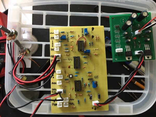
I can show you the photos, or pcb layout if it helps somehow. |
|
|
Back to top
|
|
|
elmegil
Joined: Mar 20, 2012
Posts: 2177
Location: Chicago
Audio files: 16
|
| Posted: Sat Mar 25, 2017 5:49 am Post subject:
|
|
|
| MrZu wrote: | | elmegil wrote: | | So your problem is somewhere between the pots and that op amp, or the op amp itself. I'd try swapping it for another. |
I swapped ICs and it doesn't solve the problem And again I've checked every connections and compare it with the schematic. This thing drove me nuts
I can show you the photos, or pcb layout if it helps somehow. |
It's worth looking, but I make no promises |
|
|
Back to top
|
|
|
MrZu
Joined: Mar 23, 2017
Posts: 10
Location: Taiga
|
|
|
Back to top
|
|
|
MrZu
Joined: Mar 23, 2017
Posts: 10
Location: Taiga
|
| Posted: Sat Mar 25, 2017 6:16 am Post subject:
|
|
|
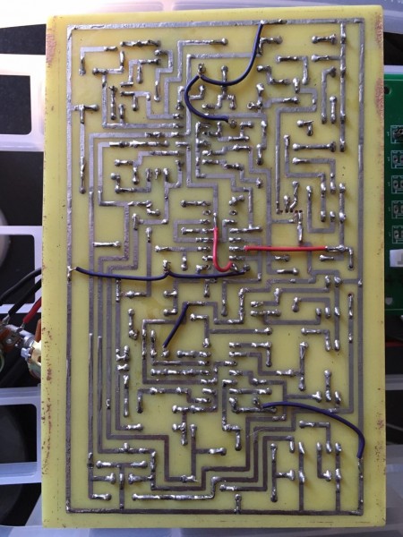
And the PCB... it is without ICs, Q1/Q2 and Q5
| Description: |
|
| Filesize: |
196.24 KB |
| Viewed: |
687 Time(s) |
| This image has been reduced to fit the page. Click on it to enlarge. |
|
| Description: |
|
| Filesize: |
195.2 KB |
| Viewed: |
677 Time(s) |
| This image has been reduced to fit the page. Click on it to enlarge. |
|
|
|
|
Back to top
|
|
|
elmegil
Joined: Mar 20, 2012
Posts: 2177
Location: Chicago
Audio files: 16
|
| Posted: Sat Mar 25, 2017 8:27 am Post subject:
|
|
|
I found 2 problems with your layout, neither of which I'd expect to have anything to do with the issue you've reported
1) you reversed the designators for R7 & R45. I think you have the right values rather than reversing them in your build, but there's not enough resolution on the top-side photo to be sure.
2) The sine round trimmer, R37, is supposed to have the wiper connected to one of the two sides of the trimmer. The symbol with the cross arrow indicates a trimmer that is wired as a rheostat, and it is common to tie the side and the wiper together on one side or the other. I don't think it matters a whole lot which side, it just determines which direction the adjust goes CW vs CCW.
Even if you swapped R7 & R45, neither of these should prevent all outputs.
I think the next thing I'd do is lift one side of R1 and see if adjusting the pots *then* will make that voltage go up and down. That completely disconnects the input section from the expo converter. If the problem is with the input then you still won't get any change, if the problem is with the expo converter or downstream it will start working at pin 1. |
|
|
Back to top
|
|
|
elmegil
Joined: Mar 20, 2012
Posts: 2177
Location: Chicago
Audio files: 16
|
| Posted: Sat Mar 25, 2017 8:30 am Post subject:
|
|
|
Also, you should note that the voltage on pin 1 is not expected to go up and down VERY MUCH. If you have a low resolution meter, it could be that it's been going up and down, but you didn't notice.
The gain on IC2a is 2K / 100K for the coarse adjustment and 2K / 3.3M for the fine adjustment, so a swing of 30V on the coarse is only going to swing about half a volt on pin 1 from all the way up to all the way down. |
|
|
Back to top
|
|
|
MrZu
Joined: Mar 23, 2017
Posts: 10
Location: Taiga
|
| Posted: Sat Mar 25, 2017 11:58 pm Post subject:
|
|
|
| elmegil wrote: | | 1) you reversed the designators for R7 & R45. I think you have the right values rather than reversing them in your build, but there's not enough resolution on the top-side photo to be sure. |
The labels swapped somehow in the CAD. I've noticed it when I build it. So everything in its place
| elmegil wrote: | | 2) The sine round trimmer, R37, is supposed to have the wiper connected to one of the two sides of the trimmer. |
Oh! I've skipped it, and it's ok now, but it doesn't solve the problem
| elmegil wrote: | | I think the next thing I'd do is lift one side of R1 and see if adjusting the pots *then* will make that voltage go up and down. That completely disconnects the input section from the expo converter. If the problem is with the input then you still won't get any change, if the problem is with the expo converter or downstream it will start working at pin 1. |
Expo conversion seems alright. So the voltage goes up and down, as you told not very much, it's about 0.5V.
So what should I do next? I'm not good at troubleshooting, but that pure signal that appears when I touch 13700 is kind of clue I can hear it, but can't adjust it  Anyway I can't touch that chip all the time Anyway I can't touch that chip all the time 
Or maybe it's 2SA798. Can I check it somehow to find out is it a bogus or not? |
|
|
Back to top
|
|
|
elmegil
Joined: Mar 20, 2012
Posts: 2177
Location: Chicago
Audio files: 16
|
| Posted: Sun Mar 26, 2017 9:31 am Post subject:
|
|
|
| MrZu wrote: |
Or maybe it's 2SA798. Can I check it somehow to find out is it a bogus or not? |
Do you have a transistor tester? That would be one thing to check, are the transistors checking out OK, testing one at a time since you have the common emitter.
You might also swap the LM13700.
If it's the 2SA798, it would be possible to substitute two hand-matched PNP transistors. Search around here for information on transistor matching, or you could even, if you have transistors on a tape, just pick a couple adjacent ones. Those are usually sufficiently matched to work reasonably well. Doing it this way doesn't really require any particular type of transistor, but be aware of the pinouts and make sure the emitters are tied together at pin 3, then collectors at 2 & 4, and bases at 1 & 5. |
|
|
Back to top
|
|
|
MrZu
Joined: Mar 23, 2017
Posts: 10
Location: Taiga
|
| Posted: Sun Mar 26, 2017 9:49 pm Post subject:
|
|
|
| elmegil wrote: | | You might also swap the LM13700. |
I have a bunch of the LM13700 with two different batch codes from the different suppliers. I've tried all of them without any success. Anyway I’ve never heard about bogus LM13700 
Actually this is my second TH VCO. A month ago I had no luck with making a XR-VCO work. I tried it with the low supply voltage source for the XR-2206 chip and "correct" batch codes. So I gave up and than I switched to the LMVCO.
| elmegil wrote: | | If it's the 2SA798, it would be possible to substitute two hand-matched PNP transistors. |
So I've tested the 2SA798 and it seems ok. Two hand-matched BC557 doesn't solve the problem anyway.
I am close to giving up again  |
|
|
Back to top
|
|
|
MrZu
Joined: Mar 23, 2017
Posts: 10
Location: Taiga
|
Posted: Tue Apr 04, 2017 6:04 am Post subject:
 |
|
|
It works! 
My AC Adapter Transformer has a little switch with DC mode. And it was switched on.  So PSU didn't work proper. So PSU didn't work proper.
Anyway, thanks! |
|
|
Back to top
|
|
|
elmegil
Joined: Mar 20, 2012
Posts: 2177
Location: Chicago
Audio files: 16
|
| Posted: Tue Apr 04, 2017 6:25 am Post subject:
|
|
|
| Those kinds of issues are simultaneously the best and the worst. Best because they're easy fixes. Worst because they're hard to find. Good job! |
|
|
Back to top
|
|
|
Scott Stites
Janitor


Joined: Dec 23, 2005
Posts: 4127
Location: Mount Hope, KS USA
Audio files: 96
|
| Posted: Sat Jun 10, 2017 4:18 pm Post subject:
|
|
|
Elmegil: you rock!
_________________
My Site |
|
|
Back to top
|
|
|
elmegil
Joined: Mar 20, 2012
Posts: 2177
Location: Chicago
Audio files: 16
|
| Posted: Sat Jun 10, 2017 4:57 pm Post subject:
|
|
|
| Why thank you, Scott |
|
|
Back to top
|
|
|
|

 Forum index » DIY Hardware and Software » Thomas Henry designs
