 Distortion Effects
Distortion Effects
by Jim Clark
The general idea behind distortion effects is to add harmonics to a sound. Either nonlinear functions or time-variant functions are needed to do this. Purely linear time-invariant functions, such as those implemented by standard filters, can only attenuate or enhance existing harmonics and not produce new ones.
Distortion using Nonlinearities
The most common approach to implementing distortion is to use a monotonic nonlinearity (one where the output level is an increasing function of the input level). The Nord Modular has a number of modules that implement such monotonic nonlinearities - the Shaper, Clip, Overdrive, and Quantizer modules.
Less common is the use of non-monotonic nonlinearities to create distortion. In the Nord Modular the WaveWrapper module is characterized by a non-monotonic nonlinearity. The distortion provided by this module is more extreme than that produced by the monotonic nonlinearities.
The following patch, designed by Wan Kemper, includes almost all Nord Modular modules that can distort audio signals, including the Shaper, Clip, Overdrive, WaveWrapper and Quantizer modules. These are strung in a series beginning with the most gentle distortion (the Shaper module) leading to more and more severe distortion (WaveWrapper and Quantizer). This ordering allows a wide range of distortion from subtle to radical.

Figure 1. Serial distortion patch, including many different nonlinear modules to distort the input (W. Kemper).
Multiband Distortion
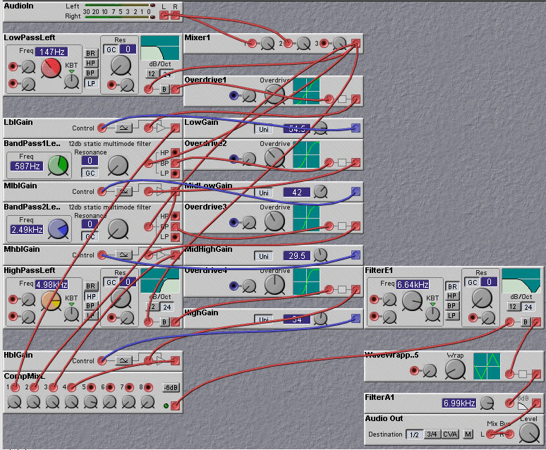
Figure 2. Four-band distortion (aka "Quadrafuzz").

Figure 3. An "exciter" patch, which adds high frequency harmonics to the input (K. Thommen).

Figure 4. Another "exciter" patch (R. Hordijk).
Distortion using Feedback
Tim Walters I found a new (to me, anyway) type of distortion on the NM--feeding the output of the ring modulator back to the modulation input. (For some reason I couldn't get this to work with the gain control module.) I quite like the sound of this technique, and this is my favorite patch so far using it. It's a bouncy sequence on one pitch (controlled by the keyboard). Knob 1 controls the input to the ring modulator, which effectively controls the distortion and makes the overall effect more staccato or legato. Knobs 2 and 3 make it wackier. Knob 4 turns it off.
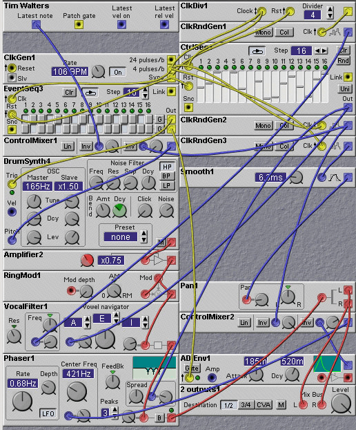
Figure 5. A distortion created by feeding back the output of the ring modulator to its input (T. Walters).
Rob Hordijk
wrote:I never did see it done with the Ring modulator module but there are some related types of distortion. Have a look at the accompanying patch with four worked out examples of similar types. 1) The basic idea is to simply feedback the output of a mixer module to one of its inputs. If the feedback signal would be more than 'unity gain' (mixer knob fully open) a potential oscillation situation might occur. But up to and including 'unity gain' an interesting situation occurs, the signal is boosted outside the digital headroom space and the output is simply clipped. The clippoint in the NM is at 256 or -256 units (4x64 units). To reduce the clipped signal back to a normal level the amplifier module set to x0.25 is used. A peculiarity of this feedback is that there is a one sample delay in the feedback, its always the outputvalue of the last sample that is fed back to the current sample. This creates a so called 'integrator', the main ingredient of a filter where each pole is actually made with an 'integrator'. The fact that it is actually the previous sample that is fed back creates a sort of microscopic reverb effect causing the signal not only to clip but to phaseshift parts of the signal as well. This causes a 'saturated' effect, reducing the very high spectral components. This type of feedback distortion does work on the NM due to the one sample delay of the output and the perfect control on the gain. In fact the unity gain of the knob and the one sample delay combined will result in a feedback 'approaching' unity gain, preventing the mixer from starting to oscillate. There are two basic parameters to control the distortion: input level and feedback. But a third parameter can be added: symmetry. By adding a constant 'voltage' to the input the mixer is pushed into an assymmetric behaviour introducing even harmonics and changing the dynamic behaviour. Using a LFO instead of a constant value creates a PWM-like effect in the sound. 2) Adding a 6 dB HP filter in the feedback line introduces some more timbre control with a strong resonant character at very high feedback levels. 3) Using a clipper to control the outputlevel instead of reducing the level back to x0.25 makes the clipping sound more sharp as well. (my favourite) 4) And a HP filter together with the clipper. In most cases input signal levels should be pretty high and the LFO level about half the level of the input signal.

Figure 6. Another module feedback distortion technique, this time using mixer modules (R. Hordijk).
Polynomial Distortion
Any nonlinearity has the potential to create new harmonics in a signal. For most nonlinearities, there are actually an infinite number of haonics generated. Of course, most of these will be filtered out by the high frequency cutoff of the analog signal chain in your system, and aliased to lower frequencies by the digital signal chain. In some situations, the user may wish to have greater control over the production of harmonics and, in particular, perhaps restrict the creation of new harmonics to a small number.
The creation of a fixed, finite, number of harmonics can be achieved with distortion functions whose input/output mapping can be expressed by a finite order polynomial.
The Chebyshev polynomials have this property : Tn(cos(theta)) = cos(n*theta). So if you make a linear combination of these polynomials, you keep an harmonic sound and you add frequencies in the spectrum. You can find Chebyshev's polynomials with this formula : T0(t)= 1 T1(t)= t Tn+1(t)-2*t*Tn(t)+Tn-1(t)=0 I like this kind of distortion because it is not too harsh. You can adjust the resulting spectrum with the Kn 1-4. Use Kn 6 to prevent internal digital clipping.

Figure 7. Chebyshev polynomial distortion technique (T.).
Steve (Rowboffin) says:
As far as I understand it, using a Chebychev polynomial as a waveshaping function has the effect of transposing the harmonics in the source by a certain amount depending on which polynomial is used. For example, if you shaped a sine wave with the 2-order Chebychev (2x^2-1) the effect would be to transpose it up an octave (i.e. 2nd harmonic) . Basically the nth Chebychev function will transpose the frequencies in the source to their nth harmonic. I've played with Chebychev functions a bit, but the problem I encountered with the higher order functions was that some of the multiplication used in them would cause the sugnal to exceed the internal headroom and thus cause digital clipping. Thomas says: That's why I introduce an amplifier for the input. But it reduces the bit depth and introduce an another kind of distortion which works like the quantizer module. I think that the only solution is to compute the chebitchev's polynomials at 24 or 32 bits for a 16 bit input (for an example) and to apply dithering to go back to 16 bits. Rob Hordijk says: In fact in the formula for the even numbered polynomials the -1 in 2*X^2-1 is not a fixed 'one' but the peak level of the momentary ampltude of the input waveform. The formulas only produce single, clean n-th harmonics if the the amplitude of the input sine particle is exactly 1. So everything depends very much on the input level. In more practical terms a DC component is added to the waveform when taking the second power, which should be removed by subtracting a level of one from the resulting waveform. Another way of removing the DC component is to use a simple highpass filter, 6 db is enough as any highpass filter will suppress DC infinitely. So before adding the terms use a hp filter for every even numbered polynomial instead of adding or subtracting 1. In this case you don't have to use very big numbers and clipping for the higher numbered polynomials can probably be avoided. These functions work very nice on high resonance filtered waves, doing strange things to squarewaves. Yet another way is to use X*ABS(X) instead of X^2, e.g. X-a(X*ABS(X)). Its not a proper Chebyshev function but yields a related sonic result. The ABS function can be conveniently made with a Diode module set to Full. Steve says: Yes, this was why I didn't think altering the input level was an ideal solution to the problem of internal clipping. The form of the polynomials I have here says that the input signal is assumed to vary from 1 to -1: i.e. the peak magnitude of the waveform is 1, as you say. I now understand a bit better why that must be so: thanks, Rob Rob says: Using any other waveform or using different amplitudes does not get the same spectrum as a sinewave with amplitude 1. But higher harmonics are added, so it distorts. Personally I quite like the effect on resonant filters like in the ChebbyBass patch, it can give a subtle distortion on the resonance. But as Thomas said it can be used on audio as well, preferrably when there's not much dynamics, so compress heavily until everything is within something like 3dB.
Distortion using Time-variant Systems
It is a little-known fact that distortion can be generated using linear systems. These systems, however, have to be time-varying. That is, their input/output mapping function, while linear, has to change with time.
If the time-variation of the system parameters is periodic, and this period is a harmonic of the input signal fundamental frequency, then the output of the time-varying system will contain harmonic components. If the period of the time-varying system is not harmonically related to the input signal, or if the time-variation is not periodic, then the output signal will have non-harmonic components. While the creation of non-harmonic components may produce interesting results, it is not what is usually referred to as distortion, so we will not consider it further here. We will restrict our notion of distortion to be those systems which create new harmonics. Thus we will only look at time-variant systems where the time variation is periodic and related to the fundamental of the input signal.
You might argue that these systems are really nonlinear rather than linear, because the transfer function between the input and output can be written as a nonlinear function. And you would be right. But, nevertheless, it is often worthwhile thinking of systems as time-variant rather than nonlinear. Consider the following distortion patch in which the main signal path is directly through a linear element, in this case a filter. The filter cutoff frequency is varied by a control signal derived from the input signal. Since the time-variation is periodic (for a periodic input), the output of the system is harmonic, and by our definition, is a distorted version of the input signal. Try it on an external input signal, such as voice, and compare the results to other distortion techniques!

Figure 1. Linear time variant systems (a time varying filter as distortion producers (J. Clark).
Warming up Distortion
A common criticism of "stomp-box" distortion units is that they don't sound very good when applied to synthesizer sounds. Some would take this to mean that the designers of distortion boxes just concentrate on getting them to sound good for guitars. Part of the problem is that guitar waveforms have some nice properties which permit good results to be obtained from applying distortion, properties which most synthesizer sounds don't have. These properties are: simple harmonic structure and smooth, controllable, decay. As we have noted above, the primary effect of distortion is to add harmonics. If a sound already has a lot of harmonics the distortion will just alter the level of the harmonics. If there are inharmonic frequency components, the harmonics added by distortion will tend to emphasize the inharmonic nature of the sound. Both of these effects will tend to result in a "harsh" sound.
We can do some things to improve the sound provided by passing a synthesizer sound through a distortion effect. The first of these is to restrict the harmonic structure by applying distortion separately to each voice in a polyphonic patch, rather than to the sum of all the voices. That is, you should apply distortion in the mono area rather than in the poly area. The following patch allows you to compare the sound obtained using distortion on each voice versus that obtained by using distortion on the summed voices.

Figure 2. Applying distortion on each voice instead of on the summation of the voices (J. Clark).
Another technique is to filter the sound to simplify its harmonic structure. This is the same technique that we used in the chapter on "analog-sounding" filters, where we used a filter (designed by Rob Hordijk) to limit the high frequency content of sounds so that they fit into a mix better. The following patch shows how we can obtain a nicer sounding distortion effect using this filter.
Figure 3. Filtering before applying distortion results in a less harsh sound (J. Clark).