Workshop Rob Hordijk
 Workshop Rob Hordijk
An electronic music instrument consists of three parts. At one side there is the human interface to play the instrument, at the opposite side is the sound synthesis engine and in between these two parts is the "intelligence" part which has to translate the signals from the human interface to the synthesis engine. In the last decades many synthesis techniques have been developed and the developments in computer technology has helped in developing the "intelligence" part. In contrast the human interface has not really seen much development. In most cases traditional instrument interfaces have simply been adapted to enable musicians trained to play that traditional instrument to play without having to learn a new instrument. But the synthesis methods and the intelligence that drives it are so flexible that there is a definite need for an expressive interface that, helped by the intelligence, can get the most out of the synthesis engine. Undoubtedly the next twenty years will see the development of new interfaces that are more suitable for expressively playing the electronics.
Today I will talk about the synthesis engine. In the other workshops some will talk about the intelligence part, for instance the workshop on swarm music. And there is an installation present where a video camera signal is used to control the sound, so a gestural human interface.
As said there are many highly advanced techniques and for a musician it is very hard to understand how it all works. And when things get very complicated it is often useful to look if there is some common denominator at the heart of these techniques and start to build up from there. I will try to prove that there is such a common denominator. In essence pitched musical sounds are a dynamically changing complex structure of repetitious waveforms with a certain pitch sensation, loudness contour and characteristic timbre. The waveforms consist of cycles and many synthesis techniques are based on producing and manipulating these cycles. A single cycle can be seen as the accumulation of a series of sine and cosine partials of certain amplitudes and by being able to handle these partials individually theoretically any sound conceivable can be made. The structure of the sound is defined in the frequency domain, which is basically a description which partials will be present at a given moment in time, for instance through a series of spectral plots. Next the data in the frequency domain is converted into the time domain, which is the actual signal or recording describing the vibrations of the air pressure when the sound is actually played. This method is commonly referred to as additive synthesis, probably using repeated Fourier transformations to do the conversion between the frequency and time domain. Regrettably the method needs so much data in such a rate that in practice it is very hard to design an implementation that allows to easily and expressively be played in real time. However, simplified models like the drawbar organ have become very popular.
In general any simplification will imply a certain characteristic sound and put these instruments in their own class. Still many believe that sound synthesizers must be used to imitate already existing traditional instruments. But this is a limited view, I believe its better to see electronic music instruments in a class of their own as they are so much more that just imitators. In my opinion they sound at their worst when having to imitate. If they can do imitations, they can most certainly do exiting proprietary stuff even better.
To overcome the need to handle big bulks of data the analog modular synthesizers from the sixties have used the subtractive synthesis method. The popular conception is that this method does not build brick by brick but tries to take the opposite approach by using a signal that contains at least all the partials needed and simply remove what is not needed in the signal. Filters do the removal of partials as they can remove lots of partials in the same operation. By using waveforms that contain all partials of a certain pitch or noise for unpitched sounds the quality and controlling possibilities of the filters define how accurate the method will be in practice. But to be theoretically perfect the filters would have to be so complex and need so much dynamic control data that probably the same amount of data would be needed as when using additive synthesis. Again simplifications are made. In fact subtractive synthesis as used in "analog" synthesizers and their "virtual analog" digital equivalents can better be seen as a form of formant synthesis where resonant filters are used to create strong but easily controllable formants. So the reason why the sawtooth and pulse waveforms are used as the raw material to be filtered has much more to do with how these waveforms excite the resonant filters than with their spectral content. The sharp transients, these are the flanks in the waveform plot where the level suddenly changes from one extreme to the other, are what "fires" the resonant filters. These transients contain an enormous amount of "energy". They have to, as when such a waveform directly drives a speaker this is the moment when all the mass of the speaker has to be moved from one extreme to the opposite extreme. In the resonant filter this energy is transformed into a "ripple" lagging the transient in the waveform, which creates a strong formant at the resonant frequency of the filter. Sweeping the resonant frequency of the filter creates a musically expressive sweeping formant with only a single parameter to be controlled. More expressive results can be obtained by sweeping two or more formants, at the cost of extra filters and controllers.
The sawtooth waveform is extremely easy to generate both analogue and digitally. In an analog sawtooth oscillator the waveform is created by charging a capacitor, an electronic component that can be charged by a current, similar to the rechargeable batteries in modern mobile phones. In comparison a capacitor can store only very little charge, but it can be fully charged and discharged almost instantaneously. By charging the capacitor in a controlled rate the voltage over the capacitor rises. When the voltage reaches a certain level a relay circuit like a transistor switch is used to instantaneously discharge the capacitor after which it is charged again. The discharging moment creates the transient in the sawtooth waveform. On analog oscillators it will still take a little time, for instance in the popular Minimoog synthesizer this time is set to about 1.5 microseconds. This will make the frequency behaviour slightly non-linear, which can be corrected by a trimmer control called "high frequency tracking".
The relationship between the charging current and the generated frequency is linear, doubling the current will double the frequency. The ear however perceives frequency in an exponential way, it "hears in octaves". This means that a frequency perceive by the ear as three times higher than another frequency, has an actual frequency that is four times higher when expressed in Hertz. So the analog sawtooth oscillator needs a circuit to easily transform octave data into the right currents. This device is called an exp/lin converter. The synthesizers built by Moog in the sixties used a 1Volt/Octave signal in the exp/lin converter to drive the oscillator and this has become the standard for analog synthesizers. So the 1V/Oct signal is translated into the proper current in the exp/lin converter. The circuitry that does this conversion can easily drift on changing temperatures and temperature compensation must be built in. The quality of analog oscillators depends mostly on the drift behaviour and accuracy of this exp/lin converter. Good quality analog circuits are costly and it is wise to get the best quality one can get, don't be pennywise but pound-foolish with oscillators.
The digital sawtooth oscillator algorithm is incredibly simple, in essence it is just a single addition instruction. By repeatedly adding a certain fixed value to a register the value in the register will increase, just like the charge in the capacitor increases by the charging current. At a certain moment the register will overflow and an overflow condition will be set in the DSP. If simple integer arithmetic is used and the register is allowed to fold back on overflow it is not even needed to "discharge" the register as this is implied in the fold back. If the DSP does not allow for fold back the register can be "discharged" by subtracting the maximum value the register can hold. This can in many cases be conveniently done by an AND instruction with an operand that has all bits set. If floating point arithmetic is used a modulus function can be used to "discharge" the register. Or alternatively rounding the result in the register to the nearest integer, which in this case will be one, and subtracting the result from the value in the register. In this particular case the value to be added must be a fractional value between zero and one. Using integer arithmetic using 24 or 32 bits and a sample rate of 96kHz and allowing fold back is the preferred way to implement the digital sawtooth, it's the simplest, most efficient and fastest method and the integer result can instantly be used to scan waveform tables and delay lines.
With the sawtooth signal a lot of things can be done, in fact most synthesis methods use a sawtooth signal at their heart to drive their synthesis engine. As mentioned before, on the old analog synthesizers it can drive the resonant filter. But the waveform can also be manipulated in a more "constructing" way to obtain different waveforms with specific desirable properties. The common pulse and triangle waveforms on the analog synthesizer are constructed from the sawtooth waveform. The pulse is constructed by comparing the level of the waveform to a fixed or slowly varying voltage, the output of the compare circuit is the pulse waveform. The triangle is constructed by folding down the upper half of the sawtooth waveform. From this triangle a sine wave can be constructed by passing the triangle through a device with the right non-linear function, in cheap synthesizers two diodes or more properly a more expensive circuit using a balanced modulator. There are analog synthesizers that use another type of analog oscillator that in first instance generates a triangle wave and a square wave and then constructs the sawtooth wave by multiplying the square with the triangle, but for sake of clarity I will not go deeper into this type. From now on it is important that there is a sawtooth waveform, no matter how it is generated.
Roughly there are three types of manipulations possible on a waveform, it can be modulated in amplitude by passing the momentary value through some sort of function that might or might not be controlled by another varying signal, it can be modulated in time by smoothly shifting the waveform forward and backward in time or it can be made to "make a jump in time" by prematurely restarting the cycle. These techniques are respectively called amplitude modulation or AM, frequency modulation or FM or oscillator synchronisation or sync. If the aim of these techniques is to create a new waveform from an existing one it is common to talk about "wave shaping". To control the amplitude a multiplier is needed. On analog synthesizers the multiplication circuit is either a VCA or a Ring modulator, digitally it is a single signed or unsigned multiply instruction. Here shows one of the first big advantages of digital modular synthesizers over analog modular synthesizers. The last invariably have a very limited amount of VCAs and Ring modulators. Both are not very accurate due to component tolerances that might be up to 10%. They also most likely exhibit leakage of controlling and modulating signals on the output. In contrast the digital multiply instruction is at least accurate within the bit depth of the system and does not leak. And as it is only a single DSP instruction many multiply operations can easily be done, although some scaling of the inputs and output might be necessary, this depending on the actual system. On the Clavia Nord Modular many modules have AM inputs that are actually signed multiply operations. These can always be used as a VCA or a Ring modulator. Many complex mathematical functions can be made by using multipliers, mixers to do the additions an constant values in a scale between arithmetically minus one and plus one. There might be a difference between the units one has to provide to the system and the actual arithmetic values, on the Nord Modular 64 units arithmetically equals plus one, so a multiplication by 64 "Clavia" units is the same as multiplying by one and would in this case leave the signal unchanged.
Several interesting functions be easily implemented, but I won't go into the details, as they can be looked up in the standard math textbooks. Some simple but useful functions I will briefly mention. The function to generate a triangle wave from a sawtooth of amplitude one is to take the absolute value of the sawtooth times two minus one or ABS(Saw)*2-1. Using a Taylor-series function this triangle can be transformed into a sinewave. Chebyshev polynomials are well known and can be used to generate the harmonic partials from an amplitude one sine wave. If coded efficiently these functions can in many instances be faster than interpolated table lookup methods.
An interesting experiment is to raise a sine wave to the power of two by feeding the sine wave in both inputs of a Ring modulator. The result will be a sine wave twice the frequency. AC coupling at the output of an analog ring modulator will block the DC component that this function inherently produces. This signal can be added to the original signal. Raising the sine wave to the power of three will produce a signal with the original sine and the third harmonic. Basically these are oversimplified Chebyshev polynomials of the order 2 and 3. They can be very useful to introduce second or third harmonic distortion on the formant produced by a resonant filter.
Digitally the sin^2 function behaves less ideal as there is no AC coupling to remove the DC component. The solution is to use a simple 6dB high pass filter set to a very low frequency, as any high pass filter will block a DC component, this works as this DC component has a frequency of zero Hertz and this frequency will be infinitely suppressed by any high pass filter. The sin^3 function will not produce a DC component and can be used on any signal without the need for the high pass filter.
A function similar to the sin^3 function is the function sin*AB (sin). On first sight the resulting waveform looks very similar but the last function produces all odd harmonics instead of only the third. A listening test will quickly reveal the audible difference. Basically any non-linear function can be used this way to amplitude modulate any audio signal, results may range from a great sound to totally havoc, but there are no rules, anything is allowed as in the end its all a matter of taste.
Frequency modulation is based on smoothly shifting the waveform backwards and forwards in time. To do this, another waveform is required to control the shift. The waveform to be modulated is called the carrier wave and the waveform that is used to modulate the carrier oscillator is called the modulator. The modulation process can be applied at several points in the carrier oscillator, the exponential frequency value can be modulated or the linear frequency value can be modulated. Using the exponential frequency value to apply the modulation to can quickly create enharmonic results, so this is of less value. On an analog oscillator linear modulation can be implemented by adding the modulating signal as a current to the current that is charging the capacitor. Regrettably it is difficult to do this in a reliable way so only few of the more expensive quality analog oscillators offer an input for linear modulation. Digitally it is no problem at all, the momentary value of the modulating waveform is simply added to the linear frequency value on the output of the exp/lin converter and before the addition takes place. To avoid enharmonic results the ratio between the frequency of the modulating wave and the frequency of the carrier wave should be kept constant in a simple ratio. The amount of modulation applied is denoted by the modulation index. The value of the modulation index is the frequency deviation of the carrier divided by the frequency of the modulating waveform. If the ratio is constant and the modulation index is constant a waveform is produced that has the same harmonic spectrum for all musical notes. This harmonic spectrum depends also on the phase relationship of the carrier and modulator, so preferably these should be locked in phase to get a stable waveform with a stable harmonic spectrum. To keep the modulation index constant it should be corrected for each frequency on the musical scale. Luckily the relation between the modulation index and the pitch is very simple, it suffices to multiply the modulating waveform by the original linear frequency parameter from either the modulating oscillator or the carrier oscillator before it is added to the carriers frequency parameter. If this condition is met, increasing the amplitude of the modulating waveform will simply brighten the timbre and create a similar type of timbre control as sweeping the resonance frequency of a resonant filter, effectively creating a single expressive parameter that can be easily played by a controller like a knob or a modulation wheel. The modulating waveform can be basically any waveform, but for the carrier oscillator it is best to use a waveform without any strong transients as these transients can get shifted in and out of the resulting waveform. This might sound quite harsh. This seems less a problem if a square wave is used as the carrier, probably due to its symmetrical nature. The sine wave and triangle wave seem to always perform very well as carrier wave, but take care with sawtooth waves.
On a digital oscillator not only the linear frequency parameter can be modulated but the actual output can be phase modulated by adding the modulating signal directly to the output signal and applying a modulo function on the result to make the resulting waveform fold back to the minus one plus one range. The advantage is that if self-modulation is used, so the carrier wave is its own modulating wave, there is no pitch shift if the modulation amount is increased due to an increase of a DC component in the output. Also here it pays to multiply the modulating waveform with the linear frequency parameter before the actual modulation is applied. If feedback is applied to the linear frequency parameter the DC component will shift the pitch, which can be overcome by using a high pass filter on the modulation input. But even a simple 6 dB high pass filter tends to resonate if it is fed back, even through the carrier oscillator, and this will make the carrier oscillator unstable at higher modulation levels.
An interesting case is if the carrier oscillators frequency is set to zero hertz, by using a value of zero for the linear frequency parameter. This can only be done on digital oscillators; they can even be set to a negative frequency by negating the frequency parameter. The result of frequency modulation of a zero frequency carrier oscillator is a signal that will inherit its pitch from the modulating oscillator and has a strong formant area in its formant spectrum which place depends solely on the modulation index. Rule of thumb is again that the sound brightens if the index is increased. This implementation can never produce enharmonic results if the modulating signal isn't already enharmonic. Using a square wave as modulating waveform will produce the timbre result of an analog technique called softsync.
If the modulating waveform is not scaled to the linear frequency parameter the modulation index will increase if the pitch is lowered. The effect is that the formant structure will not shift along with the pitch but a fixed formant area is created in the overall sound spectrum. Analog filters have a control that defines the amount in which it will track the pitch. One hundred percent tracking will make the filter follow the pitch and no tracking will give a fixed resonance frequency. It is customary to set the filter tracking somewhere between fifty to seventy-five percent. To implement a similar function with FM it suffices to use a cross fader between the modulating waveform and the scaled waveform, so the points before and after the multiplier that is used to do the scaling. The position control of the cross fader will have the same function as the tracking control on the filter.
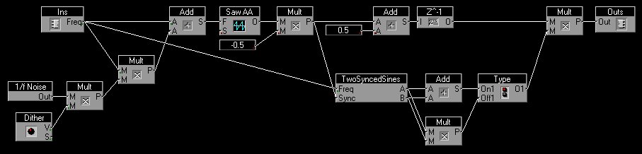
Oscillator synchronisation lets an oscillator restart its waveform in synchronization with another waveform. Analog oscillators that are capable of synchronizing commonly use the transient in the waveform to synchronize to. A transient detector generates a very small pulse that is used to prematurely discharge the capacitor. This implies that on an analog sawtooth oscillator the synchronized wave restarts with the maximum negative value from where it ramps up. On digital oscillators it is common to restart the waveform at the upward zero crossing point. It is also common to let the oscillator synchronize on an upward zero crossing point in the synchronizing waveform. To detect this zero crossing point the current sample is compared with the previous one and if the current one has a positive value and the previous one a negative value the zero crossing point is detected. At this moment the register that holds the current sawtooth waveform value is filled with a certain value instead of doing the addition. Oscillator synchronization introduces a transient in the synchronized waveform at the moment it is synchronized. This makes the current level change to a certain fixed level of either zero or the maximum negative extreme value. This "sync" transient is very audible and the characteristic timbre effect of a sync sweep is caused partly by the changing magnitude of this transient. On waveforms like the sawtooth this magnitude changes gradually and doesn't contrast to much with the timbre of the original wave. But with sine and triangle waves the contrast is greater and doesn't always sound very well. In many cases it pays to suppress this transient by applying an envelope over the waveform. This envelope is called the mask and the technique is called nasked sync. The mask must be synchronized to the synchronizing waveform, so it is obvious to construct the mask from the synchronizing waveform. It is preferrable that if the mask is applied the gradient at the start of the next cycle is equal to the gradient of the previous cycle, but this depends a bit on the waveform to be synchronized. If this waveform is a sinewave it is best to use a half bell-shaped curved mask, if it is a sawtooth, a square or a triangle wave a simple downward slope can be used for the mask as well. This downward slope can easily be derived from a rising sawtooth by applying the function x'=-0.5 * x + 1. In other words by inverting the sawtooth, halving the amplitude and adding one. On an analog synth the VCA can probably be modulated by an amount control that fades between full modulation and full signal. In this case it suffices to invert the sawtooth, feed it to the VCA modulation input and set the amount control half open. To get the half bell-shaped mask the sawtooth can be soft clipped by maybe a log-type function before it is converted into the mask. An expressive oscillator can be build by using two synchronized sinewaves and multiplying them before a half bell-shaped mask is applied. The gradient of a sin^2 wave is zero degrees at the start of its cycle, so multiplying the two sinewaves also gives a gradient of zero degrees as the startpoint of the cycles are synchronized to the synchronizing sawtooth oscillator. In this case it is the synchronized waves that produce the zero degree gradient at the start of the cycle and the mask that causes the zero degree gradient at the end of the cycle. Setting the two sinewaves to different frequencies above the frequency of the synchronizing sawtooth oscillator that supplies the mask will create a timbre with an expressive formant character. The sinewaves can be manipulated before or after they are multiplied together, but before the mask is applied. The mentioned sin^3 and sin*abs(sin) functions perform very well making the timbre more talkative. Using a joystick or any other X-Y controller to offset the frequencies of the synchronized sine waves allows for very expressive timbre control, but envelopes and LFOs can of course be used as well. Applying FM on the two sine waves can also give expressive results.
Example patch for FM with easily controlable modulation index

Example patch of masked sync
Example patch of masked sync with FM

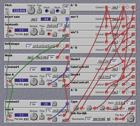
Example patch of masked sync for the SyncModular softsynth