 Help Creating Waveform
 Help Creating Waveform
Grant Ransom wrote:
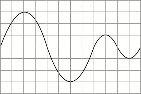
I've a problem creating this kind of waveform.

The problem seems to be that the first sinewave is larger than the second... And be able to do it as 'economically' as possible. I've tried some sync, AM and FM things but no joy. Anyone got any Ideas?
Florian Anwander wrote:
Now the problems is: the first sinewave is a deeper frequency. I think you could do the following (sorry, but I have no NM here in the office, so I can't send a patch)
A Master-Osc clocks a step sequencer with three steps. The sequencer generates Gate signals. The first two steps are low, the third step is high.
Slave-Osc #1 does a sine of the same frequency - Slave-Osc #2 does a sone one octave lower
The outputs of the oscillators are fed to separate VCAs. The VCA #1 is controlled directly by the stepsequencers output. The VCA #2 is controlled by the inverted signal of the stepsequencer. Now you simply have to mix the output signal of the both VCAs in the appropriate relation.
Grant Ransom wrote:
Thanks, I'll try this, I avoided this solution because I find the sequencers don't deal with the high range of the keyboard too well... But you never know.
Lennart Regebro wrote:
Maybe the clock dividers are better at that? I haven't tried it. Something like the attached patch (Assym01) might work (it's untested, don't have a modular here). Robs idea about modulating the mst/slv signal seemed good too. Possibly the divider solution could be used to modulate the mst/slv signal too (Assym02) but I guess this doesn't improve the jitter problems even if it works.
Rob Hordijk wrote:
Strangely enough the patch produces the waveform when a S&H is inserted after the clock module (and the division rates 2-3 should be 3-2).
Audio Processing wrote:
Not exactely the same waveform. The second adjacent sinus has the same frequency. The X-Fade Input is always at zero.
Rob Hordijk Wrote:
You're right. Actually the second divider isn't necessary at all.
Here is a comparison of the S&H divider (toggle flip-flop) and the clock divider, with and without filtering of the divider signal. The 96kHz of the S&H definitely pays off, the filter can improve soundquality even more. On a waveform like this one would probably like to have it sound as clean as possible.
When the clock divider and filtering is chosen and the osc is set at a somewhat higher frequency (e.g. G#5) one can clearly hear how jitter affects the fundamental frequency by introducing a gritty vibrato.
Rob Hordijk wrote:
Have a look at this example.
A S&H and a logic inverter module are used to make a squarewave half the frequency of the basic sinewave, which in turn modulates the frequency by processing the grey signal. The crossfader is used as the amplitude must be processed by the same signal and I think this is probably the cheapest way, else a gain controller with the button pressed would do the same job, but then the high cycle instead of the low cycle would have the highest amplitude.
The S&H works at the full 96kHz, also its yellow input (Clavia confirmed this!). Making a frequency divider this way works quite well up to a high pitch range. But there is some frequency jitter as the squarewave has to "fit" in the 96kHz sampleclock. The jitter gets worse when the pitch is increased.
Btw jitter is similar to aliasing, but aliasing is a deficiency in the amplitude level and jitter is an instability of the frequency. Jitter is worse as jitter modulates the fundamental pitch. Aliasing introduces very high inharmonic frequencies which in many cases can be filtered out, but if there is jitter on the fundamental frequency there is just nothing you can do about it. A trick is to add a Chorus module as it can mask the jitter a bit.
Theoretically a digital synthesis system should use a sampleclock of around 5MHz(!) to lower jitter in all cases to a level where it cannot be perceived anymore. But it will take another generation before DSPs might become so fast that a system like the NM can run on such a sample clock. Luckily jitter is only generated in oscillators and if the proper algoritms are used digital oscillators can be made virtually jitter free. But with e.g. hardsync its almost impossible to avoid a little jitter.
When used directly the frequency divider works quite well, the jitter on a squarewave is actually perceived as a tiny amount of pwm, but when using this signal to do frequency selfmodulation, as is done here, it superimposes the jitter on the modulated signal. A filter in the feedback path of the frequency divider is used to reduce the jitter a bit. Lowering the filters cutoff frequency changes the oscillators frequency a bit. Using more poles can make things even worse as filters have a considerable phase shift which might influence the frequency even more. So, there is no "ideal" solution to your problem, but I think this example should work well as long as you don't play in the highest octaves.
Grant Ransom wrote:
Ah... this is a 'flip flop' isn't it?
Rob Hordijk wrote:
Yes, a toggle type. It doesn't matter that the inverter is slower than the S&H as it stays on for some time. You can hear the difference if you listen to the red output of the S&H and the yellow output of the inverter.
Grant Ransom wrote:
It seems to do the job, I was trying a circuit using 2 tuned osc's and a fundamental pulse at 66% to AM them. Lots of clicking though. As usual, your grasp of logic and it's application have helped immensely.
Rob Hordijk wrote:
The clicking is quite annoying, its mostly caused by a one sampleclock delay in a module. The order in which you place the modules is important, if module A is placed before module B than module B will use the output of module A immediately, but module A will use the output of module B on the next sampleclock. This can cause timing differences if modules are used in parallel and their outputs combined. Only one sample can already cause an annoying glitch. Matters get worse in a big patch where ther are some modules already deleted, their empty space will be filled by the next placed modules, which in turn might be calculated before modules already in the patch. Sometimes I work out a patch and the I completely rebuild it placing the modules in the exact oreder they should be. Many times this can reduce glitches but it is not at all guaranteed. Adding a delay module can sometimes help as well, but is rather expensive for only a few samples delay. A button switch module from the mixer section simply set to ON and placed at the right moment can also help sometimes.
A useful technique is to suppress the signal whenever a glitch might occur. In this case the output just holds its previous value for one sample clock. This technique is called masking and I know that Clavia is looking into this technique to improve the sound quality. I hope they come up with some wizardry in V4.
Audio Processing wrote:
See this...
Roland Kuit wrote:
You can draw a 'wavetable'. Take the SinOsc as clock for 2 serial sequencers, the output of the those into a mixer--output. Draw your pic into it. Somewhere in the patch archive I've done a cubic cosine and a moph from sine to saw wave.
Maybe a programmer can develope a program from a picture to sequencer settings? There's a program that creates sequencer settings out of *.wav files.
Wout Blommers wrote:
The Wav2Seq program works only on V2.1, but a program Pic2Seq already exists. You can draw your thing in CuBase or other sequencer programs. (Use the grid) Set the sequencers in the Editor on 'record', play the sequence on the computer and "It's in!!!"
Results in...?

Using a Smooth Module...

Dave Peck wrote:
BTW, Grant, what is the application? What's the waveform for? Just curious.
Grant Ransom wrote
:The waveform image I made was actually a simplified version of the wave I wish to create, and I'm now getting pretty close (with your help).
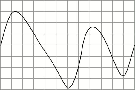
This is the actual wave. It's even less 'symetrical' than the sine version I drew before. You could guess the sound I'm creating from this wave?

Here's an unfinished version of the sound I was trying to get. I'm tweaking to get the hard velocity sound warmer, and to get the characteristic 'bark' of the original.
Resulting in this waveform (picture by Jan Punter)
