| Author |
Message |
Inventor
Stream Operator

Joined: Oct 13, 2007
Posts: 6221
Location: near Austin, Tx, USA
Audio files: 267
|
 Posted: Wed Apr 09, 2008 6:02 pm Post subject:
Biometric HID in ChucK Posted: Wed Apr 09, 2008 6:02 pm Post subject:
Biometric HID in ChucK
Subject description: Making human body sensors that work with ChucK |
  |
|
I was thinking about ways to control the ChucK-based effects setup that I plan to create for playing the guitar, and the whole biometric thing occurred to me. This has traditionally been done with pedals, sensing one or two axes, but what if we did it other ways?
The knees are well suited for a potentiometer input each, leading us to situations like the performer moving up and down or jumping to access various effects triggers or parameters.
Something like a high resolution dance pad would provide two axes of control, or the performer could be moving around within a large Theramin, providing at least one axis of control. Also a pedal that moved like a mouse and took in mouse-clicks would be a great computer interface for controlling the effects.
Hmm, I will have to go read up on ChucK's HID features now... Thoughts, ideas or suggestions, anyone?
_________________
"Let's make noise for peace." - Kijjaz |
|
|
Back to top
|
|
 |
Inventor
Stream Operator
Joined: Oct 13, 2007
Posts: 6221
Location: near Austin, Tx, USA
Audio files: 267
|
| Posted: Thu Apr 10, 2008 1:34 am Post subject:
|
|
|
I did a little Googling on the topic and discovered that Biometric is a term for fingerprint and retina scanning devices that perform identification. HID, or Human Interface Device, is the correct term.
There is a standard that governs HID devices on the USB and ChucK's joystick interface seems the best for that. I don't know of any hardware vendors that provide interfaces yet, though.
I was thinking that a good way to do a mouse would be to make a pedal and mount it on an optical mouse, then make a large, sturdy mouse pad for it. You'd have to be careful not to step on it too hard, but it would allow you to control a MAUI interface with your foot while playing the instrument. Or really, a trackball might be the best for that...
_________________
"Let's make noise for peace." - Kijjaz |
|
|
Back to top
|
|
|
Kassen
Janitor


Joined: Jul 06, 2004
Posts: 7678
Location: The Hague, NL
G2 patch files: 3
|
| Posted: Thu Apr 10, 2008 2:21 am Post subject:
|
|
|
http://www.ultimarc.com/
These nice people sell boards that will convert buttons and/or variable resistors (like joysticks but also inertia sensors) to HID-joystick.
Mainly meant for MAME but if it works with MAME it should work with ChucK; a joystick== a joystick.
There were also other ones, more specialised in continuous controls but I forgot. Maybe Arduino? At least this stuff exists so that's already months saved :¬)
_________________
Kassen |
|
|
Back to top
|
|
|
Inventor
Stream Operator
Joined: Oct 13, 2007
Posts: 6221
Location: near Austin, Tx, USA
Audio files: 267
|
| Posted: Thu Apr 10, 2008 6:14 am Post subject:
|
|
|
Yay, good find Kassen! This is another area that has grown tremendously in the past decade, as I remember only crude prototypes being available for arcade controls long ago. These boards are so easy - just hook up to pots and switches and plug into ps/2 connector!
Can ChucK handle more than one joystick? Their A-PAC module, which is the one that handles both pots and switches, has two versions: one does two joysticks with up to four axes, and the other does a single joystick with six axes. The one with dual joysticks also does buttons, so that would be the one to choose I guess.
It will be months before I can give this a try, but at least there is plenty of time to plan and get things figured out.
_________________
"Let's make noise for peace." - Kijjaz |
|
|
Back to top
|
|
|
Kassen
Janitor
Joined: Jul 06, 2004
Posts: 7678
Location: The Hague, NL
G2 patch files: 3
|
| Posted: Thu Apr 10, 2008 8:53 am Post subject:
|
|
|
| Inventor wrote: | | Yay, good find Kassen! This is another area that has grown tremendously in the past decade, as I remember only crude prototypes being available for arcade controls long ago. These boards are so easy - just hook up to pots and switches and plug into ps/2 connector! |
I strongly recommend you use USB, I'm not even sure joystick HID objects can be connected to ps/2... but fortunately those pac's support USB (I have no experience with them myself though).
But yeah, home arcade controls are quite advanced these days. I use a joystick that uses the exact same parts as Japanese arcade machines myself. The difference in feel is striking.
| Quote: | | Can ChucK handle more than one joystick? |
Yes, and they can be identical as well (this was briefly a bug some time ago but Spencer stamped it out).
| Quote: | Their A-PAC module, which is the one that handles both pots and switches, has two versions: one does two joysticks with up to four axes, and the other does a single joystick with six axes. The one with dual joysticks also does buttons, so that would be the one to choose I guess.
It will be months before I can give this a try, but at least there is plenty of time to plan and get things figured out. |
Sounds good. You may want to look into pressure sensitive resistors and inertia/tilt sensors as well.
_________________
Kassen |
|
|
Back to top
|
|
|
Inventor
Stream Operator
Joined: Oct 13, 2007
Posts: 6221
Location: near Austin, Tx, USA
Audio files: 267
|
| Posted: Thu Apr 10, 2008 1:07 pm Post subject:
|
|
|
I see now that the Ultimarc products are all USB. So I'll need an A-PAC version 2 for $37 (has a more logical potentiometer configuration), a USB cable, and some pots + wires + heat-shrink tubing from Digi-Key and that should do it. Total cost with shipping will be about $70 or so, not bad for a custom dual-knee HID sensor. Oh, I'll also need some rods and leg fasteners of some sort, so call it $100.
Then I can put the reverb on the right knee, the feedback on the left knee, and move around to control them. I sure hope I actually do this cause it sounds way cool.
I looked into the other sensor types, particularly pressure sensitive resistors - they look useful also. I'll have to think of what to do with them, but some drum-type thing sounds like a possibility.
_________________
"Let's make noise for peace." - Kijjaz |
|
|
Back to top
|
|
|
Kassen
Janitor
Joined: Jul 06, 2004
Posts: 7678
Location: The Hague, NL
G2 patch files: 3
|
| Posted: Fri Apr 11, 2008 12:09 am Post subject:
|
|
|
There are also materials that change resistance when they are pulled and of course tilt-sensors may be useful... I wouldn't go with pots as pots would depend on some sort of harness that would also restrict movement.
You may want to look up Perry Cook's (known from the STK) paper on controllers and interfaces for the NIME, I think the Shakers Ugen started as a experiment using tilt sensors. His paper has interesting observations and a very down to earth and fun approach I think will appeal to you.
http://www.cs.princeton.edu/~prc/CHI01Web/chi01.htm
http://www.nime.org/2001/papers/cook.pdf
(cook wrote a lot on this but that paper is the funniest and most general, searching his name and "nime" will get you a lot more)
My friend Nescivi has a lot of experience with this stuff, she's working with sensors attached to a dancer who in turn controls SuperCollider, would you like me to bring this topic to her attention? Of course more advanced sensors are harder to get and more expensive.
I wish I could remember the name of those other encoders. These Ultimarc ones are aimed at home-arcade setups, not at more general A-D conversion. I think you'd be better off with more continuous channels and less on/off buttons.
Oh, and I hope you add your thoughts to your "ChucK diary", I bet people will like to see how this evolves and how and why you make choices.
_________________
Kassen |
|
|
Back to top
|
|
|
Inventor
Stream Operator
Joined: Oct 13, 2007
Posts: 6221
Location: near Austin, Tx, USA
Audio files: 267
|
| Posted: Fri Apr 11, 2008 7:20 pm Post subject:
|
|
|
Now that's pointing me to the experts, Kassen! By all means mention to your friend about my project because maybe she can think of some better way to do it. To clarify, I want to sense the angle of my knees so that I can do things like assign feedback to the left knee, reverb to the right knee, and then sit/stand/move to change those parameters.
Unfortunately at this time the only way I know to do it is with a potentiometer at the knee. I'd put metal rods on the body and the knob of the pot and attach those to thigh and leg with straps. Still, there may be problems with the pot arrangement and slipping/motion of the rods relative to the straps.
I don't care if it's moving the guitar or jumping around or walking across the floor or whatever, but there must be some way to vary parameters like that which works along with guitar playing.
Maybe your friend will have some ideas.
Thanks for the links, I see the use of switches and force-sensing resistors but not potentiometers. There must be problems with pots for some reason. I wonder how the professionals measure knee angle? Perhaps using a string that changes resistance when pulled like a rubber band, secured at either side of the knee?
_________________
"Let's make noise for peace." - Kijjaz |
|
|
Back to top
|
|
|
nescivi

Joined: Mar 23, 2005
Posts: 94
Location: Montreal
|
| Posted: Sat Apr 12, 2008 10:19 pm Post subject:
|
|
|
NIME is indeed a good place to look for similar projects of people who have been working on this stuff for a while, you will surely find some papers with some ideas for what you want to do.
For the knees, I think bend sensors may be the best, and easiest to integrate in clothing, you can sew them into long kneepads or something. I haven't worked with those though, so I don't know how good the response is.
As for interfaces: Arduino seems to be very popular, as it is quite cheap but flexible to program, but their input to the computer is some serial protocal (via USB), and I don't know whether Chuck has support for it already.
My favorite is the Create USB Interface, by Dan Overholt, which can be had for $50, and that shows up as an HID interface, and should work with Chuck through their HID implementation.
I just saw a student here in Montreal at Concordia last week, who had made some shoes with built-in pressure sensors and accelerometers to measure tilt to control sound, which was a nice idea too. |
|
|
Back to top
|
|
|
Inventor
Stream Operator
Joined: Oct 13, 2007
Posts: 6221
Location: near Austin, Tx, USA
Audio files: 267
|
| Posted: Sat Apr 12, 2008 11:22 pm Post subject:
|
|
|
Thanks, nescivi, I like your ideas. The Creative USB Interface looks good, but requires programming and design. The Ultimark A-PAC version 2 seems like it would be simpler to use, or am I missing something? Anyway, I really like the shoe-sensor idea, with two force-sensing resistors at heel and toe position, wired in series to create a potentiometer. That would work out well, I suppose. I looked into the bend sensor, and it is definitely better than a potentiometer with rods attached to it. I don't know which way to go until I get there, but thanks for the help!
_________________
"Let's make noise for peace." - Kijjaz |
|
|
Back to top
|
|
|
Kassen
Janitor
Joined: Jul 06, 2004
Posts: 7678
Location: The Hague, NL
G2 patch files: 3
|
| Posted: Sun Apr 13, 2008 7:05 am Post subject:
|
|
|
| nescivi wrote: |
As for interfaces: Arduino seems to be very popular, as it is quite cheap but flexible to program, but their input to the computer is some serial protocal (via USB), and I don't know whether Chuck has support for it already. |
Actually, I think Arduino uses a paralel port for communication. USB would get involved as many modern laptops don't have those ports anymore. ChucK support for paralel port is planned but not here yet. I think one of the issues was finding a good cross-platform library, that's the last thing I heard about it.
| Quote: | My favorite is the Create USB Interface, by Dan Overholt, which can be had for $50, and that shows up as an HID interface, and should work with Chuck through their HID implementation.
|
Right now ChucK needs HID devices to be a mouse, keyboard or joystick and data only flows from the device to ChucK, not the other way around. This is somewhat limiting, of course. It would be good to be able to talk to tablets (as a tablet, not a mouse) as well and do stuff like force-feedback or make keyboard leds blink.
_________________
Kassen |
|
|
Back to top
|
|
|
Inventor
Stream Operator
Joined: Oct 13, 2007
Posts: 6221
Location: near Austin, Tx, USA
Audio files: 267
|
| Posted: Sun Apr 13, 2008 8:53 am Post subject:
|
|
|
Yes, though I would prefer to use the Creative USB Interface because it is more flexible, more powerful, and can be used for many other purposes, however the PIC software is only available on Windows OSes.
I have only Mac and soon Ubuntu Linux... Well, there is the old gaming PC, that runs Win 95 or something, I might possibly use that for PIC development... But anyway I'm hoping to just wire something up, plug it in, and have it talking to ChucK right off the bat, which is why I mention preference for the Ultimark A-PAC Version 2.
That one has six channels for six potentiometers, so with each shoe requiring only one channel that still leaves me four channels for other inputs. The pressure-sensitive resistors would need to have about 100 k Ohms in parallel each, and be wired in series to form a potentiometer. The output signal of the pot would vary according to where the weight is shifted. Hmmm, for that matter perhaps one would only need one such sensor in the toe part of the shoe, wired with a pair of fixed resistors to form a potentiometer.
The reason for a resistor in parallel with each force-sensing resistor is that a force-sensing resistor is an open circuit with no contact and then it kicks in at 100 k Ohms when you press on it, which goes down to 20 k Ohms or so at full force. So when it was in the unused open position, it would not look like a pot, and would probably fail the A-PAC self-test which is not preferred. So putting 100 k Ohms in parallel with the sensor makes "sense" (ouch, bad pun).
This is great, we've gone from a general concept to fleshing out the details of a working HID just by forum posts. What's missing right now is a manufacturer of force-sensing resistors... I think I'll go dig that up now...
_________________
"Let's make noise for peace." - Kijjaz |
|
|
Back to top
|
|
|
blue hell
Site Admin

Joined: Apr 03, 2004
Posts: 24499
Location: The Netherlands, Enschede
Audio files: 298
G2 patch files: 320
|
| Posted: Sun Apr 13, 2008 10:15 am Post subject:
|
|
|
| Inventor wrote: | | Well, there is the old gaming PC, that runs Win 95 or something, I might possibly use that for PIC development... |
I don't think win 95 and 98 are supported for the microchip development environment anymore. There are older versions available for download, but those will not work to develop newer chips ...
_________________
Jan
also .. could someone please turn down the thermostat a bit.
 |
|
|
Back to top
|
|
|
Inventor
Stream Operator
Joined: Oct 13, 2007
Posts: 6221
Location: near Austin, Tx, USA
Audio files: 267
|
| Posted: Sun Apr 13, 2008 10:50 am Post subject:
|
|
|
| Blue Hell wrote: | | Inventor wrote: | | Well, there is the old gaming PC, that runs Win 95 or something, I might possibly use that for PIC development... |
I don't think win 95 and 98 are supported for the microchip development environment anymore. There are older versions available for download, but those will not work to develop newer chips ... |
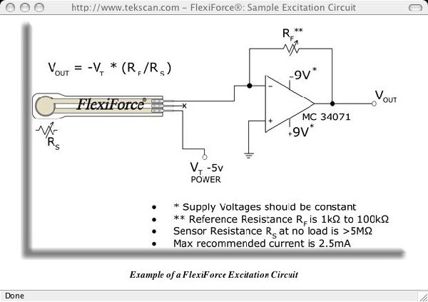
Alas and alack, wherefore goest thou, o Windows? I should have realized that, thanks Blue Hell. So the PIC solution is out. Googling again I have discovered FlexiForce Force Sensors and I can get a 4-pack of their 100-lb sensors for $39 + shipping, not bad at all. They have a recommended drive circuit that linearizes the sensor over the full 0V to +5V range, but that would require a voltage-input USB interface.
Instead, I can just hook the sensor up as the lower branch of a voltage divider and use a 470 k Ohm resistor for the other. These sensors require no parallel resistor as they begin sensing at 1 M Ohm and decrease to 50 k Ohms at full load, or lower for higher force than 100 lbs. The conductivity is linear with force, so the resistance has a 1/F shape to it. The divider approach produces output signal from 1V to 3V in a mostly linear transfer function (OK, kind of curved but good enough).
So far that's the circuitry plan, so one sensor at the "ball", or "toe" of each shoe, got the sensor model number (A-201-100), got recommendations for mounting the sensor, got interface, wiring is simple... I think the system is fairly well described, now I'll just think about it and determine a connector/wire harness and see if anyone offers more comments.
_________________
"Let's make noise for peace." - Kijjaz |
|
|
Back to top
|
|
|
Inventor
Stream Operator
Joined: Oct 13, 2007
Posts: 6221
Location: near Austin, Tx, USA
Audio files: 267
|
|
|
Back to top
|
|
|
Kassen
Janitor
Joined: Jul 06, 2004
Posts: 7678
Location: The Hague, NL
G2 patch files: 3
|
| Posted: Sun Apr 13, 2008 12:26 pm Post subject:
|
|
|
I still think a USB HID interface would scale better and be more straighforward. Admittedly this idea would save money....
_________________
Kassen |
|
|
Back to top
|
|
|
Inventor
Stream Operator
Joined: Oct 13, 2007
Posts: 6221
Location: near Austin, Tx, USA
Audio files: 267
|
| Posted: Sun Apr 13, 2008 12:57 pm Post subject:
|
|
|
| Kassen wrote: | | I still think a USB HID interface would scale better and be more straighforward. Admittedly this idea would save money.... |
I bet you're right, Kassen. Maybe I should plan this in stages. See, now that I've got a basic working unit in mind, my brain is running amok with plans for AM wireless transmitters, building my own pre-amp into the onboard sound card, and things like that. But the simplest plug-and-play approach would seem to be best for the first try.
I can imagine a setup where the shoe-sensors are each transmitting around 1 MHz and I make a simple fixed-frequency AM receiver for input to the right channel of the onboard soundcard. Then there are no body wires, just a little circuit board with a 9V battery tied into the shoelaces. Further, once doing a transmitter I could expand the system to transmit the guitar as well, completely freeing me from the wires. The guitar can be separately demodulated and send in, amplified, on the left channel of the onboard soundcard. Then a little processing in ChucK and I'm good to go.
Obviously that's a lot more work than buying some parts and hooking them up, so perhaps I can let that be stage 2 of the plan: wireless. It would free me from all the wires, that is until someone reported me to the FCC for running illegal shoe transmitters!
Anyway, just exploring more ideas, configurations, to see where it goes...
_________________
"Let's make noise for peace." - Kijjaz |
|
|
Back to top
|
|
|
Inventor
Stream Operator
Joined: Oct 13, 2007
Posts: 6221
Location: near Austin, Tx, USA
Audio files: 267
|
| Posted: Sun Apr 13, 2008 1:27 pm Post subject:
|
|
|
Hmmm, now I've just learned about the existence of wireless USB sticks. For $80 each, they might provide a good wireless interface...
_________________
"Let's make noise for peace." - Kijjaz |
|
|
Back to top
|
|
|
Kassen
Janitor
Joined: Jul 06, 2004
Posts: 7678
Location: The Hague, NL
G2 patch files: 3
|
| Posted: Sun Apr 13, 2008 2:19 pm Post subject:
|
|
|
Yeah, Bluetooth might be a more sensible option, with less FCC issues as well :¬)
Still, it's probably a good idea to consider all options because some of the less usual ones might have artistically interesting side effects.
Fortunately we have lots of DIY hardware people around to ask questions as well!
_________________
Kassen |
|
|
Back to top
|
|
|
Inventor
Stream Operator
Joined: Oct 13, 2007
Posts: 6221
Location: near Austin, Tx, USA
Audio files: 267
|
| Posted: Sun Apr 13, 2008 8:48 pm Post subject:
|
|
|
| Kassen wrote: | | Fortunately we have lots of DIY hardware people around to ask questions as well! |
Good point, I posted a similar thread under Musical Interfaces to see if anyone replies there, seemed like the logical place to put it.
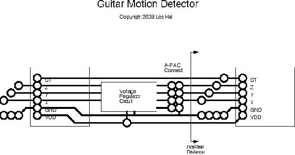
I've been thinking about accelerometers this evening, and I looked up what Digi-Key has to offer. Analog Devices makes an ADXL330 chip that sells for $12 and does three-axis sensing. It only requires four capacitors plus a voltage regulator to step down the +5V from the USB interface. It's very accurate and linear and all that jazz - the perfect little "point sensor" of acceleration.
Now here's the application. I mount one sensor at either end of the guitar, run a 5-pin cable between them, and connect to (all) the inputs of an Ultimarc A-PAC Version 2 USB interface. Then, run it to the PC with a USB cable. This clean, simple HID has no wires except those directly on the guitar so there is no "suiting up" of the performer - just grab your guitar and play.
We can then have a complete description of linear and angular guitar motion by integrating acceleration into velocity and then distance, and subtracting the two sensors to get pitch, roll, and yaw. Imagine a window with active MAUI pong elements representing the giutar in 3D space, and that image moving as the performer moves around on the stage, tracking the motion on the screen.
Once that is accomplished one can assign functions to different parts of the stage: back left and jump selects effect #1, center stage and jump clears all and resets to defaults, etc. Perhaps once an effect is selected, the six axes of control (X, Y, Z, Pitch, Roll, Yaw) are used by the effect. Run left to boost feedback, go foreward to boost reverb, jump to trigger a sampler, you get the idea.
I guess it's obvious I'm still exploring ideas since I keep moving the target, but that's a good thing for now; plenty of time to plan...
_________________
"Let's make noise for peace." - Kijjaz |
|
|
Back to top
|
|
|
Inventor
Stream Operator
Joined: Oct 13, 2007
Posts: 6221
Location: near Austin, Tx, USA
Audio files: 267
|
| Posted: Mon Apr 14, 2008 4:52 am Post subject:
|
|
|
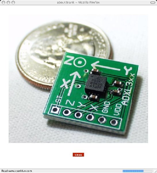
I've been studying the ADXL330 this morning. That chip is so small that I cannot possibly solder it. Fortunately, SparkFun Electronics sells a board for $35 each that has an ADXL330, the four capacitors, and a 0.1" header interface. That's a bit pricey for a $12 part on a mini board, but it is kind of specialized and necessary for the project.
The rest of the circuitry would consist of buffer amplifiers (if any) and a +5V to +3V regulator. Aside from that, it just wires up to the Ultimarc A-PAC Version 2 ($39), which plugs into a USB cable to the computer. Oh, and a button circuit is necessary for the two self-tests (well, optional actually).
I think the best place for the neck sensor is on the back side of the headstock in the center, and for the A-PAC a top-mount position behind the bridge where there is some open space on the front of the guitar. Same spot for the second ADXL330 and the regulator. Optionally, I could mount the far sensor on the back of the guitar body where the neck joins, just next to the bolt-on neck plate. There would still be enough distance to do the sensing properly and I wouldn't have wires running down the back of the neck. For that matter, it could be on a stick-shaped PCB on the front of the guitar. Just a few inches should be enough separation to make it work.
There is the possibility that the subtraction and double integration to get a distance and angle output could be done in analog circuitry on the front board. That may be necessary if the computer (and ChucK) can't keep up with the 50 Hz bandwidth of these sensors at 12 bits resolution. That could be an issue and will have to be worked out by trial and error.
Gee, this project gets simpler and simpler the more I think about it.
| Description: |
| ADXL330 Accelerometer PCB, $35 each |
|
| Filesize: |
60.78 KB |
| Viewed: |
274 Time(s) |
| This image has been reduced to fit the page. Click on it to enlarge. |
|
_________________
"Let's make noise for peace." - Kijjaz |
|
|
Back to top
|
|
|
Inventor
Stream Operator
Joined: Oct 13, 2007
Posts: 6221
Location: near Austin, Tx, USA
Audio files: 267
|
| Posted: Tue Apr 15, 2008 6:45 am Post subject:
|
|
|
This morning I spent some time reading up on the LM317 adjustable regulator, since I have some of those somewhere, to drop the supply voltage from 5V down to 3V for the accelerometers.
I've also realized I can make a "stick" circuit board using peel-n-stick resist approach, and drill it with my dremel. The "stick" would be 0.7" wide and about 3" or 4" long, depending on how much room there is to put it on the guitar behind the bridge. Said stick would run the 6-wire interface from each accelerometer to the center where the regulator circuit goes. The stick also routes the 8-wire interface to the USB board.
Then I can secure the stick with double-sided foam to the guitar and not have to run wires everywhere.
Also the regulator will need a 1k Ohm dummy load because the accelerometers draw so little supply current. The potentiometer in the regulator serves as a calibration function.
Little by little its coming together...
_________________
"Let's make noise for peace." - Kijjaz |
|
|
Back to top
|
|
|
Inventor
Stream Operator
Joined: Oct 13, 2007
Posts: 6221
Location: near Austin, Tx, USA
Audio files: 267
|
|
|
Back to top
|
|
|
Inventor
Stream Operator
Joined: Oct 13, 2007
Posts: 6221
Location: near Austin, Tx, USA
Audio files: 267
|
| Posted: Tue Apr 15, 2008 11:03 pm Post subject:
|
|
|
Oh, and I forgot to mention the circuit also has a pull-down resistor on the self-test lines to disable that feature (for use in a later version), and pads for additional 1 uF filter capacitors (6 of them). These caps will reduce the bandwidth of the sensors from 50 Hz to 5 Hz which is still quick enough to catch guitar motion, yet slowed down to the point where it can be easily oversampled by the HID/USB interface chain. This is important for correct integration of the signal in software.
_________________
"Let's make noise for peace." - Kijjaz |
|
|
Back to top
|
|
|
Inventor
Stream Operator
Joined: Oct 13, 2007
Posts: 6221
Location: near Austin, Tx, USA
Audio files: 267
|
| Posted: Wed Apr 16, 2008 6:51 am Post subject:
|
|
|
I have discovered some interesting facts that cut costs and manufacturing effort down to nothing. A Wiimote, the remote controller for the Wii, has an ADXL330Z three-axis accelerometer in it already, plus a few buttons, for only $50! No custom circuit board, no DIY, just buy a Wiimote and secure it to your guitar!
The thing is, that's only one sensor, which will tell us X, Y, and Z, but what about pitch, roll, and yaw? Well, those are derived by sensing gravity. If we neglect the dynamic acceleration, there will be a static acceleration due to gravity from which we can calculate the pitch, roll, and yaw angles. It's all documented on the web.
The Wiimote has a USB interface, so all I would need would be a 10' extender cable and that's it! Awww, gee, I took all the hardware fun out of it and turned it into a software project! Tell you one thing, I'm glad I thought it out and blogged my thoughts in this thread, saved me lots of time and effort! Just stick a Wiimote on your guitar, what a simple solution!
_________________
"Let's make noise for peace." - Kijjaz |
|
|
Back to top
|
|
|
|

 Forum index » DIY Hardware and Software » ChucK programming language