| Author |
Message |
ar2jr

Joined: Mar 29, 2008
Posts: 88
Location: San Francisco
Audio files: 1
|
 Posted: Fri Feb 13, 2009 4:21 pm Post subject:
Din Sync Shuffle Posted: Fri Feb 13, 2009 4:21 pm Post subject:
Din Sync Shuffle |
  |
|
Hello:
I'm trying to figure out how to shuffle a Din Sync clock signal. Since it would drive other din devices I don't need a divide down circuit. Any info is much appreciated.
-matia |
|
|
Back to top
|
|
 |
Luka

Joined: Jun 29, 2007
Posts: 1003
Location: Melb.
|
|
|
Back to top
|
|
|
ar2jr
Joined: Mar 29, 2008
Posts: 88
Location: San Francisco
Audio files: 1
|
| Posted: Fri Feb 13, 2009 5:14 pm Post subject:
|
|
|
what about some way of delaying/processing din clock coming from a kenton pro 2000 with an attenuator for swing.
thanks for the link though.
-matia |
|
|
Back to top
|
|
|
cthulu

Joined: Feb 07, 2009
Posts: 56
Location: Göteborg, Sweden
|
| Posted: Sat Feb 14, 2009 12:00 am Post subject:
|
|
|
I have a more or less vague idea that you could insert and "eat up" clock pulses at a regular basis to change
the speed in between the beats. But this would be a stepwise change in the swing and involve some three or
four IC's. You could most certainly do something involving an AVR chip or similar. Some sort of master clock unit...
There probably are circuits like this around. |
|
|
Back to top
|
|
|
cthulu
Joined: Feb 07, 2009
Posts: 56
Location: Göteborg, Sweden
|
|
|
Back to top
|
|
|
ar2jr
Joined: Mar 29, 2008
Posts: 88
Location: San Francisco
Audio files: 1
|
| Posted: Sat Feb 14, 2009 4:48 pm Post subject:
|
|
|
| that's a really great idea. what about if it took the clock and reset/start/stop info from an external din sync source? |
|
|
Back to top
|
|
|
cthulu
Joined: Feb 07, 2009
Posts: 56
Location: Göteborg, Sweden
|
| Posted: Sat Feb 14, 2009 5:41 pm Post subject:
|
|
|
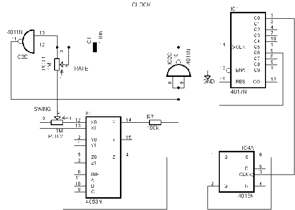
You could make that work. I don't have any DIN machines and I don't remember how it works. I think
the other two signals are really easy to realise and we have a leftover 4013 half for S/R action. Two NAND
gates are unused too. I'd need to read up on it but you can take it from here if you like. Hm... you could probably
make some really sick grooves if you put in a switch to make the 4017 reset from other counts than 6...
Last edited by cthulu on Sun Feb 15, 2009 6:48 am; edited 1 time in total |
|
|
Back to top
|
|
|
cthulu
Joined: Feb 07, 2009
Posts: 56
Location: Göteborg, Sweden
|
|
|
Back to top
|
|
|
cthulu
Joined: Feb 07, 2009
Posts: 56
Location: Göteborg, Sweden
|
|
|
Back to top
|
|
|
cthulu
Joined: Feb 07, 2009
Posts: 56
Location: Göteborg, Sweden
|
|
|
Back to top
|
|
|
211

Joined: Jul 18, 2006
Posts: 50
Location: Marseille - France
|
| Posted: Mon Feb 16, 2009 7:07 am Post subject:
|
|
|
cthulu, it looks really great !
I might be interressed building this design for my 606, I just have a small question.
Your din shuffle device seems to be only Master as it contain a clock circuit.
The overkill feature would be it can be synced as slave by an external clock.
This way, your interface could be synced by a standart midi to dinsync device.
Do you think It could be possible, as in your design the Clock pot and the lag circuit are tied together ? |
|
|
Back to top
|
|
|
cthulu
Joined: Feb 07, 2009
Posts: 56
Location: Göteborg, Sweden
|
| Posted: Mon Feb 16, 2009 7:41 am Post subject:
|
|
|
Salut!
| 211 wrote: | cthulu, it looks really great !
I might be interressed building this design for my 606, I just have a small question.
|
Definitely breadboard first. And help spot errors in the drawing prior to that... I just knocked this one up in a creative frenzy but... it's not that many parts really and the logics seems to add up.
| Quote: |
Your din shuffle device seems to be only Master as it contain a clock circuit.
The overkill feature would be it can be synced as slave by an external clock.
This way, your interface could be synced by a standart midi to dinsync device.
Do you think It could be possible, as in your design the Clock pot and the lag circuit are tied together ?
|
I really wouldn't know where to start to solve that one. Sorry. 
You would probably need to go into programming but then just about anything is possible. I'm just not an ace of a hacker...
ce tout!
oskar |
|
|
Back to top
|
|
|
cthulu
Joined: Feb 07, 2009
Posts: 56
Location: Göteborg, Sweden
|
| Posted: Mon Feb 16, 2009 7:50 am Post subject:
|
|
|
But if you have midi at your hands then you can let midi regulate the swing, check earlier on in this thread.
Eventually you could do some sort of odd fixed division like the solution in the Re-Bop thread that I started...
but then you would have to run the drummachine at a much higher tempo than the rest of the equipment and I
don't know midi that well. I'm not really compatible with modern technology and I guess that's why
I ended up here in the first place. |
|
|
Back to top
|
|
|
211
Joined: Jul 18, 2006
Posts: 50
Location: Marseille - France
|
| Posted: Mon Feb 16, 2009 9:17 am Post subject:
|
|
|
Yep I know all the (boring) tricks to add shuffle to the 606..
In fact, I ever played with some 4017 for a din synced step sequencer.
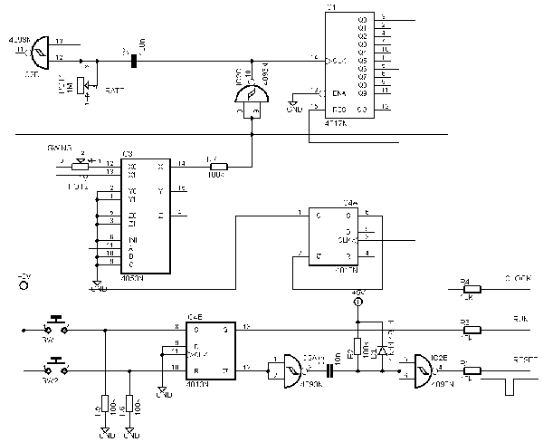
All the reset / start / stop circuit is based on CGS gate sequencer.
I sync it as slave with my 606. To sync the same devices at the same tempo, I have to divide the din clock by 6, before feeding the divided clock into a second 4017, which is the sequencer core.
I use a 4017 as clock divider and use exactly the same trick as you.
I thought it was possible to route the 6th pulse of the din sync clock to a variable lag circuit. Then replace the lagged pulse in place where the 6th pulse of the regular clock should be.
 |
|
|
Back to top
|
|
|
cthulu
Joined: Feb 07, 2009
Posts: 56
Location: Göteborg, Sweden
|
| Posted: Mon Feb 16, 2009 9:45 am Post subject:
|
|
|
Nice, so I'm not alone with that circuit. I must admit that I didn't look that much on the other sequencers
before I did the Re-Bop, because I got so inspired when I found the dbop files that I just went into a zombie
like CAD mode... and if I had done that I would probably have realised that:
A. There are amazing sequensers around on this forum. Like the Klee...
B. The minimalistic ones around are simpler than mine so I don't really fill a need.
 Oh well, you live and you learn... Oh well, you live and you learn...
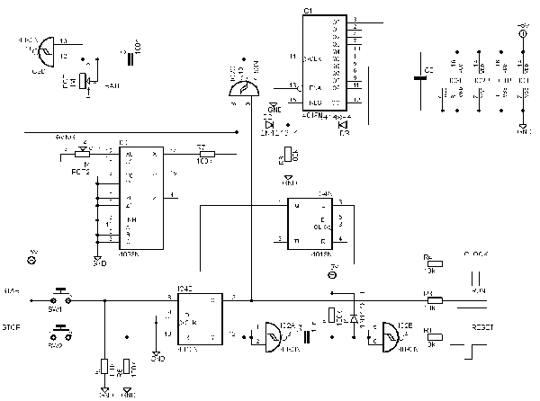
 If you cut in an xor in the clock path you can add a half clock tick by just changing states on the other If you cut in an xor in the clock path you can add a half clock tick by just changing states on the other
pin and subtract one half tick by also changing states on the other pin but on the same time as the clock and
filter away possible ripple. |
|
|
Back to top
|
|
|
211
Joined: Jul 18, 2006
Posts: 50
Location: Marseille - France
|
| Posted: Tue Feb 17, 2009 9:41 am Post subject:
|
|
|
I found some info on a german forum about the ShuffleBox you can find on Youtube.
It's PIC based. The box contain an optocoupler, one PIC and one pot.
The code count the first 6 step of the clock signal, then shift the 6 next. A the end of the 12th it simply go to the first line of code.
The author says the din signal is usually a 2ms pulse signal. Don't seems to need a real square.
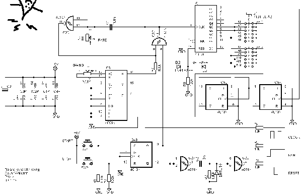
I don't know anything about PIC prog. The only thing I though with CMOS/analogue is :
- clock a 12 counter by the main clock, din signal or Pot driven oscillator
- the first 6 outputs of the counter trig a 2ms pulse generator
- the 6 last outputs trig the 2ms pulse generator thru a lag generator
- the 12 outputs are summed with an opamp creating the shuffled clock.
The harder thing is probably to find the maximum lag time who works from 40 to 200 bpm |
|
|
Back to top
|
|
|
cthulu
Joined: Feb 07, 2009
Posts: 56
Location: Göteborg, Sweden
|
| Posted: Tue Feb 17, 2009 12:13 pm Post subject:
|
|
|
I'm tempted to get on the job at coding something for an AVR processor, it shouldn't be that much work involved.
The problem is I don't have any Roland sync machines to try it on.
No swing for me... |
|
|
Back to top
|
|
|
Luka
Joined: Jun 29, 2007
Posts: 1003
Location: Melb.
|
|
|
Back to top
|
|
|
ar2jr
Joined: Mar 29, 2008
Posts: 88
Location: San Francisco
Audio files: 1
|
| Posted: Wed Feb 18, 2009 2:40 pm Post subject:
|
|
|
have to say that I am absoluetely thrilled by the course this discussion has taken. unfortinatly I sold most of my din machines except for the tr 808 and jupiter 8 so I won't be able to loan anything out for experimentation.
but if there are things that I can build and test with my set up let me know and i'll get on it.
perhaps we could develop a really nice shuffle box for all us Din Sync fanatics  i'm thinking call it "Swing 24" i'm thinking call it "Swing 24"
-matia |
|
|
Back to top
|
|
|
BOB-SNARE
Joined: Sep 26, 2008
Posts: 30
Location: Australia
|
| Posted: Mon Mar 02, 2009 1:46 am Post subject:
|
|
|
| cthulu wrote: | I'm tempted to get on the job at coding something for an AVR processor, it shouldn't be that much work involved.
The problem is I don't have any Roland sync machines to try it on.
No swing for me... |
I've done a MIDI to Swinging DINSync with an AVR. I got distracted by the sloppy MIDI timing from USB MIDI interfaces,
especially using a MIDISPort 2x2 with Ableton. Anybody know anything
about writing USB device drivers?
As far as I can tell, MOTU are the only ones who have...everybody else uses the standard usbaudio.sys
Where was I... |
|
|
Back to top
|
|
|
midgetfidget
Joined: Aug 22, 2006
Posts: 84
Location: melbourne, aus
|
| Posted: Mon Mar 02, 2009 5:00 pm Post subject:
|
|
|
Maybe some other aussies here might remember these, but a member of Clan Analogue used to make boxes call the "swing-a-lizer" or something like that.
They were kind of a din master clock that put out all types of swing, from mild to just crazy. Maybe there's schematics out there somewhere... |
|
|
Back to top
|
|
|
BOB-SNARE
Joined: Sep 26, 2008
Posts: 30
Location: Australia
|
| Posted: Mon Mar 02, 2009 6:48 pm Post subject:
|
|
|
| midgetfidget wrote: | Maybe some other aussies here might remember these, but a member of Clan Analogue used to make boxes call the "swing-a-lizer" or something like that.
They were kind of a din master clock that put out all types of swing, from mild to just crazy. Maybe there's schematics out there somewhere... |
It was the Swingchronizer. And it has MIDI out too, and reverse swing and triplet mode. I <3 swung 808.
Only problem is using it with a DAW for multi-pass recording. |
|
|
Back to top
|
|
|
|

 Forum index » DIY Hardware and Software » Developers' Corner