| Author |
Message |
Conboy

Joined: May 01, 2009
Posts: 25
Location: London
|
 Posted: Sun May 10, 2009 12:39 pm Post subject:
VCA Transistor matching Posted: Sun May 10, 2009 12:39 pm Post subject:
VCA Transistor matching
Subject description: how do I do it? |
  |
|
Being newish to this I'm unsure how to match the BC547 transistor pair.
If they are from the same batch are they likely to be matched anyway?
If not how do I match them without any special equipment?
Tried to google it but got a bit  |
|
|
Back to top
|
|
 |
LetterBeacon
Joined: Mar 18, 2008
Posts: 454
Location: London, UK
|
|
|
Back to top
|
|
|
yusynth

Joined: Nov 24, 2005
Posts: 1314
Location: France
|
|
|
Back to top
|
|
|
Conboy
Joined: May 01, 2009
Posts: 25
Location: London
|
| Posted: Mon May 11, 2009 12:22 pm Post subject:
|
|
|
Nice one Yves
Good and simple circuit ... I'll be off to buy a breadboard tomorrow then!
I did put the VCA together without matching but it sounds pretty bad! Splutter, distortion and cutting out on higher frequencies.
I am a little confused as to which components I should omit in the DC version. I left out C3 and C4 and fitted straps, but there are a number of other components with ** next to them (Q4, R24, C8, C9, D1) which I am unsure what to do with?
thanks |
|
|
Back to top
|
|
|
Conboy
Joined: May 01, 2009
Posts: 25
Location: London
|
| Posted: Mon May 11, 2009 4:12 pm Post subject:
|
|
|
I have once again discovered the depths of my ignorance and will tomorrow be building the AC coupled version.... being as that's what I need to do the job...
 |
|
|
Back to top
|
|
|
yusynth
Joined: Nov 24, 2005
Posts: 1314
Location: France
|
| Posted: Tue May 12, 2009 7:44 am Post subject:
|
|
|
| Conboy wrote: | Nice one Yves
Good and simple circuit ... I'll be off to buy a breadboard tomorrow then!
I did put the VCA together without matching but it sounds pretty bad! Splutter, distortion and cutting out on higher frequencies.
I am a little confused as to which components I should omit in the DC version. I left out C3 and C4 and fitted straps, but there are a number of other components with ** next to them (Q4, R24, C8, C9, D1) which I am unsure what to do with?
thanks |
Well don't expect to reach HIFI standard from such a simple design, still it should not distort too much, check the input levels (there are level pots to adapt the levels). If the trimming is done correctly it should work OK.
The ** components are optional, some people don't need a level indicator in their VCA  Anyway if you are not sure don't omit them. Anyway if you are not sure don't omit them.
_________________
Yves |
|
|
Back to top
|
|
|
LetterBeacon
Joined: Mar 18, 2008
Posts: 454
Location: London, UK
|
| Posted: Wed Jun 10, 2009 2:44 pm Post subject:
|
|
|
Can the circuit that was posted by Yves earlier in the thread be used to match PNP trannies too?
How come that circuit is so much simpler than Moog's circuit?
Is the Moog circuit more accurate? |
|
|
Back to top
|
|
|
yusynth
Joined: Nov 24, 2005
Posts: 1314
Location: France
|
| Posted: Thu Jun 11, 2009 9:48 am Post subject:
|
|
|
Yes the circuit above is valid for PNP provided that you reverse the power supply polarity.
That is replace the NPN by a PNP with same connection Emitter for emitter , base for base, and collector for collector, and the +15V becomes ground and the ground becomes +15V.
The Moog's circuit provides a linear current source while here the current is defined by the collector resistor. When you need to match the Vbe of two trannies the same day, the simple circuit above is efficient enough.
_________________
Yves
Last edited by yusynth on Thu Jun 11, 2009 10:19 am; edited 2 times in total |
|
|
Back to top
|
|
|
LetterBeacon
Joined: Mar 18, 2008
Posts: 454
Location: London, UK
|
| Posted: Thu Jun 11, 2009 9:54 am Post subject:
|
|
|
| That makes sense, thanks a lot! |
|
|
Back to top
|
|
|
ultrashock

Joined: Dec 10, 2009
Posts: 40
Location: Vienna.AT
|
| Posted: Wed Dec 16, 2009 2:00 am Post subject:
|
|
|
Hi!
Kindly ask you to answer the next question (sorry for repeat), but anyway:
We can measure transistors by:
- Hfe (in you budget multimeter),
- Vbe (by the stated above schemes),
- or even as diodes (by connecting base-emitter).
All this values are completely different, that's why could you please answer by what values it is important to measure the transistors:
- for Moog VCA,
- for Moog VCF,
- VCO expoconvertor,
- other purposes.
and in what nodes it is critical?
Besides aforesaid and all known SSM2210/LM394/2SC1583/MAT02 NPN pairs there are also BCM847 and BCM857 transistors (M at the end means matched). And I noticed they are also cheap (out of stock at Digikey now). So, could they be used for our purposes without matching as such a ".1%" transistors? |
|
|
Back to top
|
|
|
yusynth
Joined: Nov 24, 2005
Posts: 1314
Location: France
|
| Posted: Wed Dec 16, 2009 12:13 pm Post subject:
|
|
|
| ultrashock wrote: |
All this values are completely different, that's why could you please answer by what values it is important to measure the transistors: |
- for Moog VCA, Hfe for the differential pairs
- for Moog VCF, Hfe for the differential pairs, Vbe for the ladder transistors
- VCO expoconvertor, Vbe or diode
- other purposes.
and in what nodes it is critical?
| ultrashock wrote: | | there are also BCM847 and BCM857 transistors (M at the end means matched). And I noticed they are also cheap (out of stock at Digikey now). So, could they be used for our purposes without matching as such a ".1%" transistors? |
Yes they are definitely useable in expo converters but be aware that they are SMD components not thru-hole.
_________________
Yves |
|
|
Back to top
|
|
|
MirlitronOne

Joined: Nov 07, 2009
Posts: 78
Location: Surrey, UK
Audio files: 2
|
| Posted: Fri Feb 05, 2010 3:28 pm Post subject:
Vbe measurement - another easy way |
|
|
Apologies if this has been suggested before, but I haven't seen this idea in print.
When Vbe matching transistors, we are looking to measure about 600 mV to 1 mV or better accuracy, with a constant current source. This is exactly what the diode test facility on a cheap multimeter is designed to do. Hence, if you take an NPN transistor, connect the base to the collector, switch your DVM to diode test and connect the positive lead to collector and negative to emitter, the display will show Vbe in mV. The usual temperature and stability rules apply. For PNP transistors, just swap the leads over.
Considerations:
1. The test current is usually 1 mA, an order of magnitude greater than most circuits presented, but not, it seems, enough to cause measurement problems (at least not when I tried it).
2. Most DVMs will only measure to +/- 1 mV, only just about sufficient.
On the plus side:
1. It's cheap and simple.
2. It is a genuine constant-current measurement.
3. You're probably using that DVM to measure the Vbe anyway.
4. It's slightly better than Yves' simple rig, and you save on the power supply and resistor!
5. I've tried it and it appears to work pretty well.
_________________
Life is like an analogue sequencer. Twiddle the knobs to avoid boredom. |
|
|
Back to top
|
|
|
fluxmonkey
Joined: Jun 24, 2005
Posts: 708
Location: cleve
|
|
|
Back to top
|
|
|
MirlitronOne
Joined: Nov 07, 2009
Posts: 78
Location: Surrey, UK
Audio files: 2
|
| Posted: Sat Feb 06, 2010 1:22 pm Post subject:
|
|
|
Yes - the "GO - NO GO" tester has almost as many ICs as my Sound Lab. 
_________________
Life is like an analogue sequencer. Twiddle the knobs to avoid boredom. |
|
|
Back to top
|
|
|
intoodeep
Joined: Mar 14, 2010
Posts: 7
Location: los angeles
|
| Posted: Sat Apr 03, 2010 9:53 pm Post subject:
|
|
|
Just to clarify Yves, for the VCA circuit on your site ("a simple but effective VCA"), the matched pair of transistors (Q1, Q2) needs to be matched for Hfe, not Vbe.
Also to what % do the transistors need to be matched?
Thanks! |
|
|
Back to top
|
|
|
yusynth
Joined: Nov 24, 2005
Posts: 1314
Location: France
|
| Posted: Sun Apr 04, 2010 12:34 am Post subject:
|
|
|
| intoodeep wrote: | Just to clarify Yves, for the VCA circuit on your site ("a simple but effective VCA"), the matched pair of transistors (Q1, Q2) needs to be matched for Hfe, not Vbe.
Also to what % do the transistors need to be matched?
Thanks! |
For the VCA matching Hfe is OK, 1% is an excellent match. But because I added the trimmer A1 to compensate for unbalance, I'd say that matching within 5% is sufficient.
_________________
Yves |
|
|
Back to top
|
|
|
ultrashock
Joined: Dec 10, 2009
Posts: 40
Location: Vienna.AT
|
| Posted: Sat Nov 20, 2010 1:24 pm Post subject:
|
|
|
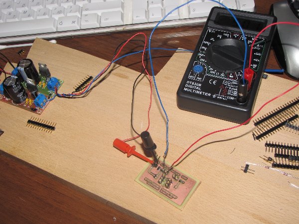
just to update the topic: I've made a universal transistor matcher - both for smd and thru holes ones both pnp and npn by the Yusynth's scheme.
smd transistors should be put and pressed to the board with some heat non-conducting material. thru holes resistors could be put directrly into collet-connectors. the direction of putting these transistors is stated as ")" or "D" with the rounded side
| Description: |
| transistor matcher in action (smd npn-transistor testing) |
|
| Filesize: |
648.53 KB |
| Viewed: |
767 Time(s) |
| This image has been reduced to fit the page. Click on it to enlarge. |
|
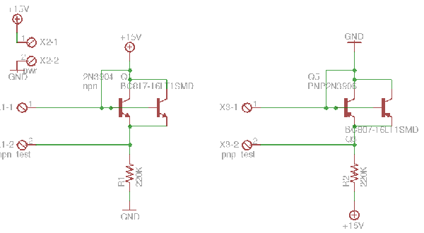
| Description: |
| transistor matcher schematic by Yusynth |
|
| Filesize: |
23.47 KB |
| Viewed: |
844 Time(s) |
| This image has been reduced to fit the page. Click on it to enlarge. |
|
| Description: |
| template for negative photo-resist (two layers), should be printed as-is without scaling |
|

Download (listen) |
| Filename: |
print_pnp_matcher.pdf |
| Filesize: |
90.04 KB |
| Downloaded: |
662 Time(s) |
|
|
|
Back to top
|
|
|
LektroiD

Joined: Aug 23, 2008
Posts: 1019
Location: Scottish Borders
Audio files: 2
G2 patch files: 2
|
| Posted: Wed Jan 26, 2011 12:14 pm Post subject:
|
|
|
| yusynth wrote: | Here is a simple though efficient circuit to match transistors.
It is important that you do not handle the transistor with your fingers (because of temperature), work in a constant temperature place and wait for one or two minutes after powering the circuit before measuring the Vbe in order that the transistor temperature being stable. |
Hi, I'm getting the same results with this as I am the HFe on my multimeter. Does this seem right? Can someone verify?
_________________
LektroiD |
|
|
Back to top
|
|
|
ultrashock
Joined: Dec 10, 2009
Posts: 40
Location: Vienna.AT
|
| Posted: Wed Jan 26, 2011 2:05 pm Post subject:
|
|
|
| It's not actually, HFE matching in Yusynth's (by Moog's) scheme above. It's more close like when you measure DIODES in Vbe in your ordinary multimeter (you can put transistors there with base and emitter pins). In what chains to which value to match see Yusynth's post above |
|
|
Back to top
|
|
|
El Mop
Joined: Aug 20, 2012
Posts: 56
Location: Germany
|
| Posted: Thu Nov 08, 2012 3:31 am Post subject:
|
|
|
| yusynth wrote: | Here is a simple though efficient circuit to match transistors.
It is important that you do not handle the transistor with your fingers (because of temperature), work in a constant temperature place and wait for one or two minutes after powering the circuit before measuring the Vbe in order that the transistor temperature being stable. |
Will this work with 12V either? |
|
|
Back to top
|
|
|
yusynth
Joined: Nov 24, 2005
Posts: 1314
Location: France
|
| Posted: Thu Nov 08, 2012 3:51 am Post subject:
|
|
|
Yes it will also work with +12V.
_________________
Yves |
|
|
Back to top
|
|
|
El Mop
Joined: Aug 20, 2012
Posts: 56
Location: Germany
|
| Posted: Thu Nov 08, 2012 4:00 am Post subject:
|
|
|
Thank You!  |
|
|
Back to top
|
|
|
imguri
Joined: Mar 04, 2015
Posts: 2
Location: alas
|
| Posted: Tue May 19, 2015 8:20 am Post subject:
|
|
|
hello,
excuse me but this post stay unclear for me. I need to match transistors for a yusynth VCA.
yusynth gives a schema to measure Vbe :
| Quote: | Here is a simple though efficient circuit to match transistors.
It is important that you do not handle the transistor with your fingers (because of temperature), work in a constant temperature place and wait for one or two minutes after powering the circuit before measuring the Vbe in order that the transistor temperature being stable. |
| Quote: | | Just to clarify Yves, for the VCA circuit on your site ("a simple but effective VCA"), the matched pair of transistors (Q1, Q2) needs to be matched for Hfe, not Vbe. |
| Quote: | | For the VCA matching Hfe is OK |
along this topic some of you advise Vbe matching way and other hFE... so i'm a bit lost... in order to match my yusynth VCA's transistors, what should i measure ? Vbe or hFE ? either ? |
|
|
Back to top
|
|
|
isak

Joined: Dec 13, 2009
Posts: 847
Location: Israel
Audio files: 18
|
| Posted: Fri May 22, 2015 4:16 am Post subject:
|
|
|
Hi
For Yusynth vca Hfe will do.
Enjoy the project.
Cheers,
Isak E.
_________________
http://www.myspace.com/mgmtrance |
|
|
Back to top
|
|
|
imguri
Joined: Mar 04, 2015
Posts: 2
Location: alas
|
| Posted: Sun May 24, 2015 5:40 am Post subject:
|
|
|
great ! now i can go on !
thank you ! |
|
|
Back to top
|
|
|
|

 Forum index » DIY Hardware and Software » YuSynth