| Author |
Message |
JingleJoe

Joined: Nov 10, 2011
Posts: 878
Location: Lancashire, England
Audio files: 14
|
|
|
Back to top
|
|
 |
Psyingo

Joined: Jun 11, 2009
Posts: 248
Location: Canada
|
 Posted: Thu May 10, 2012 2:16 pm Post subject: Posted: Thu May 10, 2012 2:16 pm Post subject:
|
  |
|
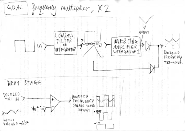
The problem with this circuit is that it's frequency dependent. But it would work on a triangle wave without the integrator. Also is an integrator not alowpass filter?
basically this is what's used in guitar octave up pedals... seems to be a full wave rectifier. |
|
|
Back to top
|
|
|
Cynosure
Site Admin

Joined: Dec 11, 2010
Posts: 1025
Location: Toronto, Ontario - Canada
Audio files: 82
|
| Posted: Thu May 10, 2012 4:37 pm Post subject:
|
|
|
That is an interesting idea. Let me know if you test it out.
I had what I thought was a brilliant idea the other day to send a signal through 2 schmidt triggers, and then highpass the outputs of each schmidt trigger. Since the triggers alternate between high and low, one filter would go high when the other is low. This would double the frequency. The highpass filter would shorten the pulse width so there is a gap between them. It would also change the harmonics and frequency response, so the mix of the highpassed outputs would have to go through a final schmidt trigger to change it to a regular square wave.
But then I found this, which is basically the same idea but uses a 4069 where I had planned on using a 40106:

_________________
JacobWatters.com |
|
|
Back to top
|
|
|
JovianPyx

Joined: Nov 20, 2007
Posts: 1988
Location: West Red Spot, Jupiter
Audio files: 224
|
| Posted: Thu May 10, 2012 7:37 pm Post subject:
|
|
|
PLEASE DO NOT TAKE MY COMMENT AS A "DO NOT TRY THIS" FLAG.
It is not.
However, there are caveats to be noted, some have already been mentioned. Indeed - you will not really understand this until you try it and see what happens for yourself. (I've done pretty much what you've suggested). If the circuit/idea pleases you, then by all means use it.
Yes, I see the comment about "ramshackle Lunetta experiments". So it may well be exactly what you want. And as such, it might be best to put a post like this in the Lunetta forum - since that's where the OP seems to be directing it's use. Again - do not take this as negative. It is not.
The folded triangle wave for frequency doubling is a long used analog modular technique, but it is not without problems even when you start with a perfect triangle. DC bias in the waveform will create problems. The amplitude halving means you need to amplify and where there is amplification, there is also amplification of noise. One friend of mine who did this tried to set up a chain of them. After only 3 stages it became unusable due to noise and DC offset. His input was a good quality triangle wave VCO.
Generating a nice triangle wave from a square wave using an integrator is not easy if you want wide frequency range. The reason is that an integrator is going to act as a lowpass filter, not as a linear slope generator. If the integrator's time constant is fixed, then so is it's cutoff frequency. Input signals above the cutoff will be attenuated, and those that are too far below the cutoff will not be very close to a triangle, more like a square wave with rounded lead-in shoulders. Also, an integrator will not give a triangle, rather it will give something kind of like a cross between sine and square. Of course, you can play folding games with a sine, but with possibly dubious results. The design will probably work to make sound that has an enhanced second harmonic and the amount of 2nd harmonic will vary with input frequency. Again - this may be ok or even desired. The best way to discover this is to punch it down onto a solderless breadboard and see what happens on an oscope. (been there).
Since this is here in the general DIY forum, I'd like to suggest that another way to get frequency multiplying (and of more than just x2) is to use the venerable 4046 PLL which can track a seriously wide range of audio frequencies. To get frequency multiplication from a PLL, one puts a digital divider into the feedback loop of the PLL. If you use divide by 2 (a simple thing) then the PLL will output a signal at 2x the input frequency. If you use a divide by 3 circuit, then the PLL will triple the frequency. I've used a PLL to do as high as x12 multiplication. It will track more than 5 octaves.
The bottom line here is - Try it. You may encounter "problems" that don't matter to you. Or you may decide it really doesn't do what you want. The proof is in the scoping and in the listening.
In fact, in the long run, you will find that using a PLL will likely result in a simpler system using fewer parts.
_________________
FPGA, dsPIC and Fatman Synth Stuff
Time flies like a banana.
Fruit flies when you're having fun.
BTW, Do these genes make my ass look fat?
corruptio optimi pessima
|
|
|
Back to top
|
|
|
Cynosure
Site Admin
Joined: Dec 11, 2010
Posts: 1025
Location: Toronto, Ontario - Canada
Audio files: 82
|
| Posted: Thu May 10, 2012 8:44 pm Post subject:
|
|
|
Yes I saw your circuit Scott. It is on my list of possible ones to try.
The only thing that even had me think about another option is that your circuit is more complicated and I don't understand it. However, if it does the job the best way possible then I might end up using it.
Why isn't there a single cmos ic that does multiplying similar to a 4040 (ie. signle in and multiples out)?
_________________
JacobWatters.com |
|
|
Back to top
|
|
|
JovianPyx
Joined: Nov 20, 2007
Posts: 1988
Location: West Red Spot, Jupiter
Audio files: 224
|
| Posted: Thu May 10, 2012 9:02 pm Post subject:
|
|
|
| Cynosure wrote: | | Yes I saw your circuit Scott. It is on my list of possible ones to try. |
Ah, yes, I remember you saying that in chat.
| Cynosure wrote: | | The only thing that even had me think about another option is that your circuit is more complicated and I don't understand it. However, if it does the job the best way possible then I might end up using it. |
It's complex only because it produces 7 different outputs. If all you want is to double - it's 2 ICs, the 4046 and a divide by 2 (there are several CMOS ICs that do div by 2).
| Cynosure wrote: | | Why isn't there a single cmos ic that does multiplying similar to a 4040 (ie. signle in and multiples out)? |
Well, the real answer is because CMOS ICs were designed for logic, not for abusing them into making audio. So engineers never thought in that direction. The IC designs that are available are ones that are so common for logic systems, the IC manufacturers could make millions at the same time so as to make the cost only pennys per IC. Note that in digital logic designs, flipflops are not used only to divide a frequency by 2. A flipflop is really a single bit memory and that is it's main function in digital logic (which is what CMOS is actually intended for).
But considering our abuse of CMOS for analog, it's because dividing is simple. To multiply without a PLL you need to know the frequency before hand. This is so that (for mul by 2) you know when to cross the zero line, which would be halfway through the first half cycle for the first transition. This can't be known in advance without complicated circuitry (or even at all possibly). With the PLL it's easy - you use the PLL to track the input. You can then divide the PLL's VCO output by 2 and that forces that PLL to run at twice the frequency of the input.
That big chunk of logic at the bottom of the schematic is really a multiple output divide by 12 circuit. If that is replaced by a simple flipflop divide by 2 circuit, you have a frequency doubler - and you can do it with 2 ICs. My first experiments with a PLL were exactly that - I used a 4046 and a 4027.
EDIT ADD: It's probably a good idea to play with a PLL sometime. Don't even worry about frequency multiplying at first. A 4046 by itself can track a signal and output a square wave of the same frequency. There are caveats about the input, mainly that it have rail to rail amplitude from the PLL's perspective. It should be a periodic waveform like a square, pulse, tri, sine or saw or similar. Guitar or voice is probably a bad input, but a synth VCO output would be ideal. Hook it up and see that it tracks. Once you have that working, then add a divide by 2 flipflop to divide the PLL VCO by 2 (that comes out of one of the 4046 pins and can be hooked directly to the flipflop). The divider then feeds a simple filter and voila, twce the frequency. Maybe do some reading on wikipedia about a PLL and how it does it's magic. It's really just a servo loop and a lot of fun.
_________________
FPGA, dsPIC and Fatman Synth Stuff
Time flies like a banana.
Fruit flies when you're having fun.
BTW, Do these genes make my ass look fat?
corruptio optimi pessima
|
|
|
Back to top
|
|
|
PHOBoS

Joined: Jan 14, 2010
Posts: 5881
Location: Moon Base
Audio files: 709
|
|
|
Back to top
|
|
|
JingleJoe
Joined: Nov 10, 2011
Posts: 878
Location: Lancashire, England
Audio files: 14
|
| Posted: Fri May 11, 2012 4:11 am Post subject:
|
|
|
Damnit phobos  I had work to do today and those videos just stole a huge chunk of my time! Thanks though, they are brilliant, I will watch the rest later I had work to do today and those videos just stole a huge chunk of my time! Thanks though, they are brilliant, I will watch the rest later 
JovianPyx, thanks for the tips I'd taken a lot of what you said into consideration, however I didn't think signal size would be a problem, I often use a comparator to generate a square wave from less than 1V saw waves, so the signal halving should be no problem.
Also with some simple op amp circuits (like summing amplifiers and differential amplifiers) or perhaps even just a capacitor to remove offset ,you can get the offset of the resulting triangle wave to something suitable for your operation. Then simply use a comparator to make it square. This should eliminate DC offset problems.
As for frequency response I knew that would be a problem but one should be able to tune the filter in to about 3 octaves of usable range, maybe add other tuned filters via a switch for different ranges. Cutoff is 1/2piRC, right? 
Also I just thought, you could invert and re-combine the resulting triangle wave from the above circuit, without turning it back into a square wave between each stage, for the next 4x input frequency stage.
Then taking that to 8x should be no problem.
Lastly, to avoid trouble with noise I'd say shield the circuit better, avoid amplification and filter signals I never thought noise would be a problem.
EDIT: Oh I just had another idea! If you put the resulting first stage triangle wave into two comparators each set to 1/3 of the triangle wave and 2/3 of the triangle wave you would get two pulse waves out of phase, then if you invert one of them and combine the two you should get a square wave with 4x the frequency of the input from only one stage of the above circuit. Due to only having come up with this one a few seconds ago, I may have made errors, please test this idea if you find discrepancy.
_________________
As a mad scientist I am ruled by the dictum of science: "I could be wrong about this but lets find out"
Green Dungeon Alchemist Laboratories |
|
|
Back to top
|
|
|
JingleJoe
Joined: Nov 10, 2011
Posts: 878
Location: Lancashire, England
Audio files: 14
|
|
|
Back to top
|
|
|
Psyingo
Joined: Jun 11, 2009
Posts: 248
Location: Canada
|
| Posted: Fri May 11, 2012 6:47 am Post subject:
|
|
|
| Oh dear.... |
|
|
Back to top
|
|
|
-minus-
Joined: Oct 26, 2008
Posts: 787
Audio files: 13
|
| Posted: Fri May 11, 2012 7:12 am Post subject:
|
|
|
| JovianPyx wrote: | | Yes, I see the comment about "ramshackle Lunetta experiments". So it may well be exactly what you want. And as such, it might be best to put a post like this in the Lunetta forum |
...actually, I think your sort of approach would go down well over on Thee Deathlehem Machine, or The S0UnD 0f L0G1C or whatever they are calling themselves right now. You should check it out. Loads of homespun inventor types over there. |
|
|
Back to top
|
|
|
JovianPyx
Joined: Nov 20, 2007
Posts: 1988
Location: West Red Spot, Jupiter
Audio files: 224
|
| Posted: Fri May 11, 2012 7:21 am Post subject:
|
|
|
Ha ha - don't start me
The idea behind a PLL is a closed loop servo system. In the PLL, there is a VCO, an input signal conditioner, a phase difference detector and a single pole lowpass filter.
The VCO outputs a square wave. The external input signal conditioner is just a schmitt trigger to square up the input signal.
The VCO is set with resistors so that it's "free running frequency" is at the center of the range of frequencies the PLL needs to track.
Once the external input signal gets past the schmitt trigger, you have 2 rectangular wave forms that may or may not be at different frequencies. One from the input, one from the VCO.
The two signals (VCO output and external input signal) are presented to the phase comparator - this is a circuit which produces a zero output if the two signals are of identical frequency and phase (phase is measured only on one edge) and an "error signal" (a servo term) when they are not. The error signal is negative if the VCO current phase is "leading" the input and positive if the VCO current phase is "lagging behind" the input. Fortunately, in a 4046, that circuit exists as part of the IC - you don't have to design it (yay!).
The comparator outputs a pulse that is wider as the phase difference increases. That's why the single pole lowpass filter is needed - it produces an analog voltage from the pulses which is intended to remain fairly stable. The analog voltage is then passed to the CV input of the VCO. The more difference there is between the two signals, the higher the voltage.
Because the VCO's CV is being generated by the error voltage, the VCO output will change depending on the phase difference.
Remember that a single pole lowpass filter has a "memory" (the capacitor). Let's make up some numbers - give the VCO a free running frequency of 2000 Hz. Let's say the tracking range is from 1000 Hz to 3000 Hz. If the input is at 1000 Hz, the comparator will produce positive pulses that will charge the cap in the filter to some positive voltage - this is applied as a CV to the VCO and causes the VCO frequency to increase. As it does, the positive pulses get more narrow and less energy is pushed into the capacitor (which will stay charged over a reasonable period of time). Once the VCO frequency and phase are equal, the phase comparator outputs zero volts and the system is considered "locked". At this point, the VCO frequency is being maintained by the capacitor (memory). Note that the cap will discharge through leakage and this will be seen by the VCO as an error voltage, but once the VCO is pushed just a little ahead or behind the input frequency, the VCO frequency is corrected by the phase comparator pulses. So even a tiny amount of phase difference is corrected automatically once the system is locked.
If the frequency (or phase) of the input signal changes, the phase comparator immediately begins to output a larger error signal which pushes the VCO to track it and stay in phase with it.
Now imagine that this locked system sees the input frequency increase to 1100 Hz - this causes a phase difference that produces an error voltage that again corrects the frequency of the VCO to match that of the input (and keeps the one edge in constant phase alignment).
Because this is real system (that is, it's built with real parts, not ideal ones) the system is never actually *perfectly* locked. There will always be a minute difference between the phase of the input and the VCO output. That's fine really, it's a known factor and in audio - it doesn't matter at all.
One of the most important things to remember is the design of the filter. If the filter is designed with a very low corner freq, the PLL will react slowly, but it will react and eventually lock. If the Fc is very high, the servo system will do what is called "hunting", that is it will cause the VCO to go faster, then slower, then faster, then slower than the input frequency, causing a warbling effect. Even there, the hunting subsides over time becoming less and less until the system stabilizes and is considered locked. When the design of the filter is optimal, the PLL reacts as fast as possible and does not overshoot (or only a little). Low frequency ranges need a lower Fc for the filter, high frequency ranges need a higher Fc for the filter. In fact, one of the fun things to do with a PLL is to design a "bad" filter on purpose, the hunting can be especially entertaining. (see the wogglebug). Note that it is possible to design such a bad filter that the system never locks. In the circuit I designed, I use a variable resistor to control the Fc of the filter. This allows adjustment to whatever I think is optimal at the moment.
One of the interesting things a PLL can do is frequency multiplication. If you put a flipflop divider between the VCO output and the phase comparator, the phase comparator is seeing a frequency exactly half of the VCO. To keep up with the input signal, the VCO must run at twice the input frequency to remain locked. (that is way cool!) It is probably wise to not get too crazy with the multiplication. The more multiplication the PLL does, the more careful one needs to be about the filter design. My design uses 12x multiplication and does not seem to suffer, so a good bit of range is available. You're probably wondering why I chose 12 - that is because it's prime factors are 2 and 3. This means that it will output nice octaves above the input as well as perfect fifths.
More technical information about the 4046 and how to use it will be found in the datasheet. Some of the datasheets are better than others, so I would suggest looking at several different manufacturer's. The one I have gives good details on how to design the loop filter and also has a very good description of the actual internal circuitry of the IC (if that interests you).
I apologize for the length of this...
_________________
FPGA, dsPIC and Fatman Synth Stuff
Time flies like a banana.
Fruit flies when you're having fun.
BTW, Do these genes make my ass look fat?
corruptio optimi pessima
|
|
|
Back to top
|
|
|
PHOBoS
Joined: Jan 14, 2010
Posts: 5881
Location: Moon Base
Audio files: 709
|
|
|
Back to top
|
|
|
JovianPyx
Joined: Nov 20, 2007
Posts: 1988
Location: West Red Spot, Jupiter
Audio files: 224
|
| Posted: Fri May 11, 2012 9:05 am Post subject:
|
|
|
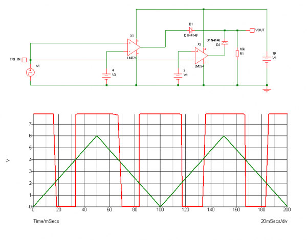
I figure I'm not really done until I post a schematic...
This is a cut down version of my PLL design. It was modified to simply double the frequency of the input. It will work best (as in stay locked and not do unexpected things) if the input signal is clean and of rail to rail amplitude.
Note that this circuit appears to be powered from ground (as Vdd) and -12v (as Vss). To make this run from say +5 volts, then replace _all_ of the ground connections seen with +5 and all of the -12v connections with ground. If you use +5 and ground as described, the input signal should travel between ground and +5 volts for best performance.
The box labeled "Div by 2" is just a single flip flop that you would use to divide frequency by 2.
The loop filter is composed to the 3.3 uF caps, variable resistor marked "DAMP" and the two 10K resistors that go back to the 4046.
Please read the 4046 datasheet for information about the 2 phase comparators. They are different and will provide different results.
I've not tested this, but I am certain it will work.
EDIT ADD: I'm adding another schematic, I've converted it to use a positive supply and ground. +V can be 3 to 15 volts. The divide by 2 counters in each schematic should be powered the same way the 4046 is powered.
EDIT ADD: PLEASE NOTE: The schematic shows a capacitor of 0.003 uF between pins 6 and 7 of the 4046. You will need to change this capacitor if you change the divider. 0.003 is for divide by 12. Use 0.02 for divide by 2, use 0.01 for divide by 4.
| Description: |
| Schematic of a PLL Frequency Doubler (Negative Supply) |
|
| Filesize: |
7.3 KB |
| Viewed: |
33080 Time(s) |

|
| Description: |
| Schematic of a PLL Frequency Doubler (Positive Supply) |
|
| Filesize: |
7.27 KB |
| Viewed: |
32955 Time(s) |
|
_________________
FPGA, dsPIC and Fatman Synth Stuff
Time flies like a banana.
Fruit flies when you're having fun.
BTW, Do these genes make my ass look fat?
corruptio optimi pessima
Last edited by JovianPyx on Sun May 13, 2012 6:04 pm; edited 5 times in total |
|
|
Back to top
|
|
|
JingleJoe
Joined: Nov 10, 2011
Posts: 878
Location: Lancashire, England
Audio files: 14
|
| Posted: Fri May 11, 2012 10:25 am Post subject:
|
|
|
| Psyingo wrote: | | Oh dear.... |
What? Cathode got your tongue? I'll assume that you are flabbergasted by the superior simplicity but maintained functionality of my latest circuit, not that you are trying to make some insulting remark.
I am actually designing another circuit now and only came back to check an old post for notes, but I can't just stand idly by while orcs roam my lands etc etc.
I'll read all about PLLs later Thanks again Mr Pyx!
_________________
As a mad scientist I am ruled by the dictum of science: "I could be wrong about this but lets find out"
Green Dungeon Alchemist Laboratories |
|
|
Back to top
|
|
|
elmegil

Joined: Mar 20, 2012
Posts: 2179
Location: Chicago
Audio files: 16
|
| Posted: Fri May 11, 2012 1:58 pm Post subject:
|
|
|
I've tried repeatedly to join Deathlehem in the last couple months, and emailed the moderator directly, and still no response whatsoever. I know that they were being spammed incredibly about the time of my first request. I even got an email apologizing and saying they'd lost my registration in the mess, please reply and they'd do it, but I got no response after that at all...
Anyone know what's up? |
|
|
Back to top
|
|
|
-minus-
Joined: Oct 26, 2008
Posts: 787
Audio files: 13
|
| Posted: Fri May 11, 2012 8:00 pm Post subject:
|
|
|
Did you use the secret handshake?  |
|
|
Back to top
|
|
|
JingleJoe
Joined: Nov 10, 2011
Posts: 878
Location: Lancashire, England
Audio files: 14
|
| Posted: Sat May 12, 2012 3:02 am Post subject:
|
|
|
| JovianPyx wrote: | | Ha ha - don't start me |
That just makes me want to
| JovianPyx wrote: |
To keep up with the input signal, the VCO must run at twice the input frequency to remain locked. (that is way cool!) |
 EUREKA! Thats brilliant thankyou! It all makes sense now! EUREKA! Thats brilliant thankyou! It all makes sense now! 
| JovianPyx wrote: | | It is probably wise to not get too crazy with the multiplication. The more multiplication the PLL does, the more careful one needs to be about the filter design. My design uses 12x multiplication and does not seem to suffer, so a good bit of range is available. You're probably wondering why I chose 12 - that is because it's prime factors are 2 and 3. This means that it will output nice octaves above the input as well as perfect fifths. |
I must be a little behind on my mathematics, surely 2x3=6 ? I'd be interested to hear a little more about getting perfect fifths or octaves, etc. I understand the basics, e.g. one octave above 100Hz is 200Hz and above that is 400Hz, and fifths are what, something like halfway between them?? wait no, I'm going to guess at 0.707 between them because thats an important number I keep seeing thrown around in electronics
| JovianPyx wrote: | | The one I have gives good details on how to design the loop filter and also has a very good description of the actual internal circuitry of the IC (if that interests you). |
Any chance you could post it please?
| JovianPyx wrote: |
I apologize for the length of this... |
Don't It is exactly what I needed thankyou, please, continue
P.S. thanks for the schematics too! I'll need to see the datasheet to fully understand the reason for half the components there, but this is significant progress anyway
_________________
As a mad scientist I am ruled by the dictum of science: "I could be wrong about this but lets find out"
Green Dungeon Alchemist Laboratories |
|
|
Back to top
|
|
|
JovianPyx
Joined: Nov 20, 2007
Posts: 1988
Location: West Red Spot, Jupiter
Audio files: 224
|
|
|
Back to top
|
|
|
RingMad

Joined: Jan 15, 2011
Posts: 429
Location: Montreal, Canada
Audio files: 4
|
| Posted: Sat May 12, 2012 5:35 am Post subject:
|
|
|
Thank you Scott for all that info on the 4046. I've always had trouble with that chip, except for using as a basic VCO, but now that I have a scope I'll sit down with the stuff you wrote and the datasheet and investigate further. It sounds like quite the multi-purpose chip.
But I'll start by trying out that divide-by-2 circuit, thanks!
James |
|
|
Back to top
|
|
|
elmegil
Joined: Mar 20, 2012
Posts: 2179
Location: Chicago
Audio files: 16
|
| Posted: Sat May 12, 2012 6:47 am Post subject:
|
|
|
| I assume that's an offer to teach it to me, minus? |
|
|
Back to top
|
|
|
Uncle Krunkus
Moderator

Joined: Jul 11, 2005
Posts: 4761
Location: Sydney, Australia
Audio files: 52
G2 patch files: 1
|
| Posted: Sun May 20, 2012 5:36 am Post subject:
|
|
|
Hey Scott!
I've known that circuit diagram for years and have been wanting to try it out. Now I've got the perfect chance, I need to make a frequency multiplyer for my new Re-Animator. I've copied your basic 2X and plan on making it an 8X. Would that work?
_________________
What makes a space ours, is what we put there, and what we do there. |
|
|
Back to top
|
|
|
RingMad
Joined: Jan 15, 2011
Posts: 429
Location: Montreal, Canada
Audio files: 4
|
| Posted: Sun May 20, 2012 6:42 am Post subject:
|
|
|
| JovianPyx wrote: | | The schematic shows a capacitor of 0.003 uF between pins 6 and 7 of the 4046. You will need to change this capacitor if you change the divider. 0.003 is for divide by 12. Use 0.02 for divide by 2, use 0.01 for divide by 4. |
I could not find a formula in the datasheet for that... is there one? I might deduce that for every doubling of the divisor, we halve the capacitance. So, since 0.02 is for /2 and 0.01 for /4, then /8 would be 0.005 and /16 would be 0.0025? Or am I way off base?
James. |
|
|
Back to top
|
|
|
Uncle Krunkus
Moderator
Joined: Jul 11, 2005
Posts: 4761
Location: Sydney, Australia
Audio files: 52
G2 patch files: 1
|
| Posted: Sun May 20, 2012 7:18 am Post subject:
|
|
|
Looks pretty spot on to me.
_________________
What makes a space ours, is what we put there, and what we do there. |
|
|
Back to top
|
|
|
JovianPyx
Joined: Nov 20, 2007
Posts: 1988
Location: West Red Spot, Jupiter
Audio files: 224
|
| Posted: Sun May 20, 2012 7:36 am Post subject:
|
|
|
| Uncle Krunkus wrote: | Hey Scott!
I've known that circuit diagram for years and have been wanting to try it out. Now I've got the perfect chance, I need to make a frequency multiplyer for my new Re-Animator. I've copied your basic 2X and plan on making it an 8X. Would that work? |
Absolutely it would work. You will need to change the capacitor on pins 6 and 7, a ballpark start value would be 0.005 uF (considering the divide by 8 circuit you will be using) and depending on what the actual frequency range is that may need to be changed up or down. This is literally a VCO capacitor, so it directly controls the range of frequencies over which the VCO will operate.
_________________
FPGA, dsPIC and Fatman Synth Stuff
Time flies like a banana.
Fruit flies when you're having fun.
BTW, Do these genes make my ass look fat?
corruptio optimi pessima
|
|
|
Back to top
|
|
|
|

 Forum index » DIY Hardware and Software