| Author |
Message |
remork
Joined: Aug 02, 2009
Posts: 25
Location: bhellgium
|
 Posted: Mon Aug 13, 2012 7:09 am Post subject: Posted: Mon Aug 13, 2012 7:09 am Post subject:
|
  |
|
i'm thinking a resistor/pot in series with the diode should give you saw to tri on the Q3 output. at the same time it would give you 0 - 50 % PWM on the Q2 output.
unfortunately, it would also change the frequency. :/
breadboarding as we speak. thanks synthmonger, simple saw VCO is just what i was looking for! |
|
|
Back to top
|
|
 |
Tomoroh Hidari
Joined: May 04, 2012
Posts: 39
Location: Vienna
Audio files: 2
|
|
|
Back to top
|
|
|
JingleJoe

Joined: Nov 10, 2011
Posts: 878
Location: Lancashire, England
Audio files: 14
|
| Posted: Wed Sep 19, 2012 3:29 am Post subject:
|
|
|
That is because the saw wave is only oscillating between the upper and lower bounds of the schmit trigger.
You can simply add an amplifier with offset removal or an input capacitor to remove the DC offset, which will get it up to the desired voltage.
By the way, remork, that doesn't work, it just increases the charge time but sets it to a constant time which does not alter with changing control voltages. I've tried a number of different variants of this VCO, with transistors in the feedback path and all sorts of things, but the initial design is the best. Except that I use an op amp buffer and a comparator for PWM.
_________________
As a mad scientist I am ruled by the dictum of science: "I could be wrong about this but lets find out"
Green Dungeon Alchemist Laboratories |
|
|
Back to top
|
|
|
Tomoroh Hidari
Joined: May 04, 2012
Posts: 39
Location: Vienna
Audio files: 2
|
| Posted: Thu Sep 20, 2012 9:03 pm Post subject:
|
|
|
ah, thanks for the info jinglejoe.
out of curiosity I breaboarded the 'single op-amp version' (http://electro-music.com/forum/topic-49901.html) of this circuit on a second breaboard using one opamp from a 324. rather than using a 100nf (or, as it says in the post 10nf) cap going to ground from the opamp input, I swapped it for a 470nF (I think - need to check again, once i'm at home), as with the 100nf I tried first I didn't get anything below somewhere between (roughly estimated) 700-1000 hz.
interestingly on the opamp version it is exactly the other way round - the saw is louder than the pulse (and i'm starting to suspect there's some logic - sorry, probably not the best word...hm, rather simple electronic principle - behind that as well).
i'm planning on recording both as soon as i manage to have an a/b comparison. i only have a software scope, but i could also try to take some screenshots of the respective waveforms with that, should anybody be interested.
_________________
~~~
http://blog.ivorybunker.com/
http://tomoroh.ivorybunker.com/
http://tomorohhidari.bandcamp.com |
|
|
Back to top
|
|
|
JingleJoe
Joined: Nov 10, 2011
Posts: 878
Location: Lancashire, England
Audio files: 14
|
| Posted: Fri Sep 21, 2012 6:44 am Post subject:
|
|
|
It's likely that the volume of the pulse is due to it's width, it will be nearly non-existant for both circuits but I suspect that it's faster with the op amp because op amps can usually output more current than CMOS, thus charging the cap faster.
Additionally the upper and lower voltage bounds of an op amp schmit trigger are usually higher and lower, respectively, than those of the CMOS variant.
_________________
As a mad scientist I am ruled by the dictum of science: "I could be wrong about this but lets find out"
Green Dungeon Alchemist Laboratories |
|
|
Back to top
|
|
|
Tomoroh Hidari
Joined: May 04, 2012
Posts: 39
Location: Vienna
Audio files: 2
|
| Posted: Fri Sep 21, 2012 9:03 pm Post subject:
|
|
|
wow, you really seem to be a walking compendium of electronics knowledge!
anyway, as promised, I did recordings of both circuits - from breadboard into the soundcard. mono, no editing or anything, except cutting the respective parts into single files... I did a sweep over the full range a 100k pot gave me (and some little extra turns towards the end on most files.)
it's, unfortunately, not recognizable in Soundcloud's waveform representation*, but the Schmitt-trigger saw shows obvious dc offset. also the saw waves on both circuits have a rather steep falling flank making them look close to pulses.... didn't get round to taking snapshots with a scope yet, but will try to the next days. anyways, without further ado, here's the audio:
40106 version:
http://soundcloud.com/ivorybunker/vco-40106-saw-21092012
http://soundcloud.com/ivorybunker/vco-40106-pulse-21092012
LM324 version: (this uses a 470nF cap instead of the 100nF in the schem)
http://soundcloud.com/ivorybunker/vco-lm324-saw-21092012
http://soundcloud.com/ivorybunker/vco-lm324-pulse-21092012
I think I definitely want to solder the lm324 soon, but for lunetta purposes it will of course be the 40106. and I was thinking there - would it be possible to use the pulse from that one as clock for a 4017? that should allow to create some sorts of custom wave form or modulation sequence at 1/n of the saw freq, innit?
*i enabled dl so if anyone wants they can have a look at it in a wave editor
_________________
~~~
http://blog.ivorybunker.com/
http://tomoroh.ivorybunker.com/
http://tomorohhidari.bandcamp.com |
|
|
Back to top
|
|
|
JingleJoe
Joined: Nov 10, 2011
Posts: 878
Location: Lancashire, England
Audio files: 14
|
| Posted: Sat Sep 22, 2012 2:55 am Post subject:
|
|
|
| Tomoroh Hidari wrote: |
it's, unfortunately, not recognizable in Soundcloud's waveform representation*, but the Schmitt-trigger saw shows obvious dc offset. also the saw waves on both circuits have a rather steep falling flank making them look close to pulses.... didn't get round to taking snapshots with a scope yet, but will try to the next days. |
I'd be interested to see that, I don't quite know what you mean.Do you mean to say that the slope is non-linear? if you used transistor buffers, I suspect them to cause that problem.
| Quote: |
I think I definitely want to solder the lm324 soon, but for lunetta purposes it will of course be the 40106. and I was thinking there - would it be possible to use the pulse from that one as clock for a 4017? that should allow to create some sorts of custom wave form or modulation sequence at 1/n of the saw freq, innit? |
Very good thinking  That seems entirely possible although sometimes the pulse is a bit low or funny shaped so it's an idea to run the pulse out of the 40106 VCO into a different 40106 inverter to buffer it and to get it back up to voltage. Then that will drive the 4017 clock nicely. That seems entirely possible although sometimes the pulse is a bit low or funny shaped so it's an idea to run the pulse out of the 40106 VCO into a different 40106 inverter to buffer it and to get it back up to voltage. Then that will drive the 4017 clock nicely.
_________________
As a mad scientist I am ruled by the dictum of science: "I could be wrong about this but lets find out"
Green Dungeon Alchemist Laboratories |
|
|
Back to top
|
|
|
JingleJoe
Joined: Nov 10, 2011
Posts: 878
Location: Lancashire, England
Audio files: 14
|
| Posted: Sat Sep 22, 2012 3:08 am Post subject:
|
|
|
I Had a look at your audio files with an oscilloscope, that weird shaped saw wave could be due to filtering effects, is there any capacitance in your signal path? The filtering in question may even be in your sound card although I doubt that as I've used mine with very very low frequency stuff with no problem.
P.S. you can also play tunes by moving the seekbar in your media player to different points in the sound file 
_________________
As a mad scientist I am ruled by the dictum of science: "I could be wrong about this but lets find out"
Green Dungeon Alchemist Laboratories |
|
|
Back to top
|
|
|
Tomoroh Hidari
Joined: May 04, 2012
Posts: 39
Location: Vienna
Audio files: 2
|
| Posted: Fri Sep 28, 2012 6:35 am Post subject:
|
|
|
I think I found out where the weird waveshape came from - I usually have this behringer 'tube ultragain" preamp between my breadboard out and soundcard/mixer in... it's the part of my equipment I wouldn't miss too much if anything bad were to happen. usually I have it in "neutral" mode without any preamp gain - anyway - looking at the signal going directly into the soundcard things are looking differently. (as in 'good')
had a try last night triggering a 4040 from the pulse out - which gave nice sub-squares and also triggering a 40106 rc osc... didn't make any recordings though and went to sleep after things stopped functioning one modification attempt later. taking up things now and trying to get that beast on perfboard...
_________________
~~~
http://blog.ivorybunker.com/
http://tomoroh.ivorybunker.com/
http://tomorohhidari.bandcamp.com |
|
|
Back to top
|
|
|
jackdamery
Joined: Apr 26, 2010
Posts: 75
Location: UK
|
| Posted: Sat Jul 13, 2013 4:58 am Post subject:
|
|
|
| Would the expo convertor transistors work better if matched for hFe? |
|
|
Back to top
|
|
|
alkopop79
Joined: Aug 21, 2008
Posts: 52
Location: London
|
| Posted: Thu Jul 18, 2013 12:09 am Post subject:
|
|
|
| Any progress on the exponential converter? I've tried it with 0-9V and it doesn't seem to work at all. |
|
|
Back to top
|
|
|
beep

Joined: May 05, 2013
Posts: 105
Location: Germany
|
| Posted: Mon Aug 26, 2013 4:44 pm Post subject:
|
|
|
here are some single supply expo converters,
perhaps it works with one of them

_________________
Is the future obsolete? |
|
|
Back to top
|
|
|
JingleJoe
Joined: Nov 10, 2011
Posts: 878
Location: Lancashire, England
Audio files: 14
|
| Posted: Wed Aug 28, 2013 2:04 am Post subject:
|
|
|
Those circuits look like they'll be really useful! though some require odd values, and I am a little confused by the 0.01 ohm input resistor, care to elaborate?
also that 10 ohm output resistor suggests that it draws a lot of current at the output which is going to create a lot of noise on the power supply if you modulate it at high frequencies (like above 10Hz) 
_________________
As a mad scientist I am ruled by the dictum of science: "I could be wrong about this but lets find out"
Green Dungeon Alchemist Laboratories |
|
|
Back to top
|
|
|
elektrouwe
Joined: May 27, 2012
Posts: 146
Location: Germany
|
| Posted: Wed Aug 28, 2013 3:37 am Post subject:
|
|
|
yes, these circuits can be useful, if you understand how they work and which of the transistors should be thermally coupled and/or matched.
The circuits don't require odd values. This schematic is made for simultaneous
SPICE simulation of some expo variants. It is common practice to insert small resistors to "measure" currents e.g. in LTSPICE, a mouse click on a resistor pin shows immediately the current flowing through this pin. Milliohm values simulate source resistances of a power supply or other non-resistive components (L,C,wire...). These components never show up
in the real circuit. |
|
|
Back to top
|
|
|
beep
Joined: May 05, 2013
Posts: 105
Location: Germany
|
| Posted: Wed Aug 28, 2013 11:35 pm Post subject:
|
|
|
could anyone, please, give me some advice, how to add one of these to the CV input of the VCO?
I'm using the design from Hendrik/metal_head
http://electro-music.com/forum/topic-49901.html
I have no idea how to add it correctly to the circuit 
greetings
_________________
Is the future obsolete? |
|
|
Back to top
|
|
|
gasboss775

Joined: Jan 02, 2016
Posts: 217
Location: Scotland
|
Posted: Sat Mar 04, 2017 1:33 pm Post subject:
Re: 40106
Subject description: VCO |
|
|
| ELEKTRICGASCHIEF wrote: | Another way of making a VCO with the 40106 is to vary the supply voltage. The relationship is far from linear and is also inversely proportional, that is the output frequency falls as the supply voltage is increased.
The other issue is that of the output amplitude varying with control voltage, if you are using the squarewave output it is easy to convert to a fixed output using 1 npn transistor as a switch, if you wish to utilise the saw / tri waveform on the capacitor this can be corrected with a subsequent vca. I used the six schmitt triggers toghether feeding a diode clipper to produce a complex atonal sound.
see below: |
Hello ELEKTRICGASCHIEF you are me in a previous incarnation I'd like to thank you for posting this such that I may now recover this schematic! |
|
|
Back to top
|
|
|
nrrrd
Joined: Jul 27, 2019
Posts: 4
Location: Oxford
|
|
|
Back to top
|
|
|
elektrouwe
Joined: May 27, 2012
Posts: 146
Location: Germany
|
| Posted: Wed Nov 27, 2019 1:42 pm Post subject:
|
|
|
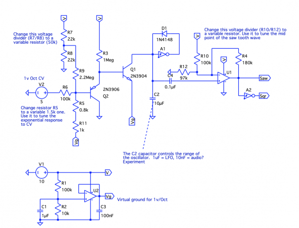
| nrrrd wrote: | | My big contribution is centring and amplifying the saw tooth |
this VCO will not behave very "well tempered". R4+R10 are a load for C2 and sink/source current that adds to the expo current. |
|
|
Back to top
|
|
|
nrrrd
Joined: Jul 27, 2019
Posts: 4
Location: Oxford
|
| Posted: Wed Nov 27, 2019 3:01 pm Post subject:
|
|
|
| elektrouwe wrote: | | nrrrd wrote: | | My big contribution is centring and amplifying the saw tooth |
this VCO will not behave very "well tempered". R4+R10 are a load for C2 and sink/source current that adds to the expo current. |
Hmmm. Should I use an op-amp to buffer the output of C2? i.e. between C2 and R4? |
|
|
Back to top
|
|
|
elektrouwe
Joined: May 27, 2012
Posts: 146
Location: Germany
|
| Posted: Wed Nov 27, 2019 11:26 pm Post subject:
|
|
|
| yes, an opamp buffer would help. You could amplify & offset with a noninverting opamp to save the extra buffer. Also think about replacing the single 40106 with 1/4 TL074... |
|
|
Back to top
|
|
|
kaputtpanzer

Joined: Nov 02, 2009
Posts: 139
Location: Cologne
Audio files: 15
|
| Posted: Thu Nov 28, 2019 5:09 am Post subject:
|
|
|
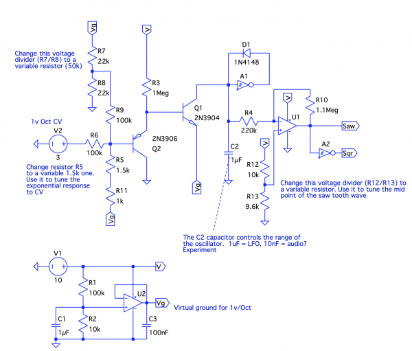
| nrrrd wrote: | Here's my take on this circuit. The expo converter is taken from Rene Schmitz's 4069 VCO, but I adapted it to work on a single sided supply (0 to 12v).
My big contribution is centring and amplifying the saw tooth wave before passing it back into an unused 40106 inverter to form the square wave. If you add a dc offset to this, before passing into the inverter, you will get pulse width modulation.
If you want to keep it strictly CMOS, you can substitute the op-amps for 4069 unbuffered inverters, but you'll have to experiment with the resistors, and reverse the R1/R2 voltage divider (I think - not tested, I just use a TL074!) |
Ah I also tried almost exactly the same thing, but somehow I don't like the sound of the sawtooth of the 40106 (there were alot of odd and weird disharmonic artefacts in the output), so I switched to CD4046 IC and used that one. Now the schematics looks abit like a single supply version of Thomas Henry's X-4046 VCO. I really love the hard sync sounds, you get with this ic. I never thought that it will be possible to get such a well tracking expo converter running of 9V or 12V, but it is possible. I use the vishay ntcs for temperature compensation and I get solid 3-4 octaves with +/- 2 cents off. Still not tracking super well over C6, but works if you adjust the scaling a bit. I think a buffer before the expo converter can help to make it even more stable and also some form of hf compensation might be needed. I am very happy with what I have already. Will post gerber files and schematics in the next months.
Last edited by kaputtpanzer on Thu Nov 28, 2019 5:29 am; edited 1 time in total |
|
|
Back to top
|
|
|
kaputtpanzer
Joined: Nov 02, 2009
Posts: 139
Location: Cologne
Audio files: 15
|
| Posted: Thu Nov 28, 2019 5:25 am Post subject:
|
|
|
| nrrrd wrote: | Here's my take on this circuit. The expo converter is taken from Rene Schmitz's 4069 VCO, but I adapted it to work on a single sided supply (0 to 12v).
My big contribution is centring and amplifying the saw tooth wave before passing it back into an unused 40106 inverter to form the square wave. If you add a dc offset to this, before passing into the inverter, you will get pulse width modulation.
If you want to keep it strictly CMOS, you can substitute the op-amps for 4069 unbuffered inverters, but you'll have to experiment with the resistors, and reverse the R1/R2 voltage divider (I think - not tested, I just use a TL074!) |
Also I would use V+ and ground for the frequency voltage divider to get the full range and its great to have another one for fine adjustments. Usually I use just a bigger resistance (R9 in your case) for this, something around 2M2. Sorry for annoying you with my ideas |
|
|
Back to top
|
|
|
nrrrd
Joined: Jul 27, 2019
Posts: 4
Location: Oxford
|
|
|
Back to top
|
|
|
dk
Joined: Feb 12, 2019
Posts: 115
Location: Europe
|
| Posted: Sun May 31, 2020 9:24 am Post subject:
|
|
|
Just out of curiosity, is there any benefit to running the expo convertor in synthmonger's circuit at a higher voltage? Greater range? Can it be done without damage to the 40106 (I assume the output will be in mV)?
Everything in my setup is 0-5V in and out, but I was hoping to get as much range out of this as possible, so thought that I could use +/- 9V just for the expo convertor and keep the 40106 running on 5V... |
|
|
Back to top
|
|
|
JovianPyx

Joined: Nov 20, 2007
Posts: 1988
Location: West Red Spot, Jupiter
Audio files: 224
|
| Posted: Sun May 31, 2020 10:15 am Post subject:
|
|
|
| dk wrote: | Just out of curiosity, is there any benefit to running the expo convertor in synthmonger's circuit at a higher voltage? Greater range? Can it be done without damage to the 40106 (I assume the output will be in mV)?
Everything in my setup is 0-5V in and out, but I was hoping to get as much range out of this as possible, so thought that I could use +/- 9V just for the expo convertor and keep the 40106 running on 5V... |
The expo converter is a voltage to current converter (current source or current sink), so the output is a current that charges the integrator's capacitor.
The amount of current passed sets how fast the cap charges.
The voltage on the 40106 input is the capacitor voltage.
It starts at 0 volts and climbs until it hits the trigger point of the schmitt trigger in the 40106 gate. Once that is reached, the cap is discharged back to near zero.
So the voltage at the input never gets high enough to damage the 40106.
As for the range of the oscillator, I would start by choosing the cap for your needs. If too large, high pitches need more current, I would rather make the cap smaller than increase the current to get higher pitches. The correct cap is the one that gives you the range you need with the voltage range you have. Experiment.
I would try it.
_________________
FPGA, dsPIC and Fatman Synth Stuff
Time flies like a banana.
Fruit flies when you're having fun.
BTW, Do these genes make my ass look fat?
corruptio optimi pessima
|
|
|
Back to top
|
|
|
|

 Forum index » DIY Hardware and Software » Lunettas - circuits inspired by Stanley Lunetta