| Author |
Message |
buildafriend
Joined: Jan 30, 2011
Posts: 47
Location: New Jersey, US
|
 Posted: Tue Sep 11, 2012 10:50 pm Post subject:
Cheapest Option for LO-FI sounding oscillators Posted: Tue Sep 11, 2012 10:50 pm Post subject:
Cheapest Option for LO-FI sounding oscillators |
  |
|
Hey people, I want to build a kind of crazy amount of super super cheap oscillators.
8-16 of them ideally. I don't want high quality. All they need is to sweep from 20hz to 20k
Must be analog.
the least amount of parts possible.
A schematic would be all that is needed.
Any advice is greatly appreciated. |
|
|
Back to top
|
|
 |
JingleJoe

Joined: Nov 10, 2011
Posts: 878
Location: Lancashire, England
Audio files: 14
|
| Posted: Wed Sep 12, 2012 11:51 am Post subject:
|
|
|
When you say analogue, what do you mean? I ask because in reality even digital ones and zeros are analogue voltages: a square wave could be either digital clock or analogue waveform.
I'd suggect the standard cmos schmitt oscillator made with a 40106. Google it.
_________________
As a mad scientist I am ruled by the dictum of science: "I could be wrong about this but lets find out"
Green Dungeon Alchemist Laboratories |
|
|
Back to top
|
|
|
buildafriend
Joined: Jan 30, 2011
Posts: 47
Location: New Jersey, US
|
|
|
Back to top
|
|
|
JingleJoe
Joined: Nov 10, 2011
Posts: 878
Location: Lancashire, England
Audio files: 14
|
| Posted: Thu Sep 13, 2012 3:52 am Post subject:
|
|
|
Hahaha thanks very much 
I use those oscillators in everything and you can get six on one chip, although they do interfere with each other a bit.
You can use an op-amp to buffer the triangle wave form the capacitor and then a differential op-amp amplifier to remove the offset and amplify it up to a reasonable size. You'll need to do a few simple calculations and maybe read up on differential op-amp amplifier circuits, alternatively you can just use a capacitor to remove all DC offset but this introduces filtering and is no good for LFOs.
Food for thought 
_________________
As a mad scientist I am ruled by the dictum of science: "I could be wrong about this but lets find out"
Green Dungeon Alchemist Laboratories |
|
|
Back to top
|
|
|
buildafriend
Joined: Jan 30, 2011
Posts: 47
Location: New Jersey, US
|
| Posted: Fri Sep 14, 2012 8:47 pm Post subject:
|
|
|
| where do you get those knobs that look like upside down mini reeses peanut butter cups? |
|
|
Back to top
|
|
|
buildafriend
Joined: Jan 30, 2011
Posts: 47
Location: New Jersey, US
|
| Posted: Fri Sep 14, 2012 9:55 pm Post subject:
|
|
|
So, I just bought four of the chips (enough chips to make 24 oscillators) which costed $2, I got 20x 4.7uF electrolytic caps ( 7 cents each ), and 8 cheapie linear 10k pots. (75 cents each).
Now I'm selecting my wall wart.
I see it says 5-7 VDC but I don't see how many milli-amps I should be feeding this guy.
Hmm... |
|
|
Back to top
|
|
|
JingleJoe
Joined: Nov 10, 2011
Posts: 878
Location: Lancashire, England
Audio files: 14
|
| Posted: Sat Sep 15, 2012 3:45 am Post subject:
|
|
|
| buildafriend wrote: | | where do you get those knobs that look like upside down mini reeses peanut butter cups? |
hahahah what the hell is that!?  sorry, that was just so surreal it made me laugh. most of my knobs are one of a kind things I scavenge or which can't be bought anymore. sorry, that was just so surreal it made me laugh. most of my knobs are one of a kind things I scavenge or which can't be bought anymore.
regarding component selection, this is an equation for the approx output frequency of a 40106 oscillator:
f=1/(R*C)
Regarding milli amps, you don't need to worry about that so much. I see you may be new to electronics so here is the basics:
Ohms law is this: I=V/R where I is current, R is resistance and V is voltage, google it for more info.
Due to this relationship between voltage, resistance and current, the amount of current an electronic circuit draws is limited by it's overall resistance and the voltage applied to it. So you don't force, say, 10mA into a circuit. You just let it draw whatever it needs from your power supply and make sure your power supply can handle the current required.
CMOS ICs are high impedance and low power which makes them great for little circuits like this, a 10mA power supply would probably be fine for one IC, but you'll find that your projects get more complex as time goes on so eventually you'll want more power for more circuitry. I'd allways try and get a power supply which can deliver 1 Amp, or 1000mA but 250mA is more than enough for your needs at the moment. I don't think I've ever seen a power supply rated for less than 250mA
_________________
As a mad scientist I am ruled by the dictum of science: "I could be wrong about this but lets find out"
Green Dungeon Alchemist Laboratories |
|
|
Back to top
|
|
|
buildafriend
Joined: Jan 30, 2011
Posts: 47
Location: New Jersey, US
|
| Posted: Sat Sep 15, 2012 12:41 pm Post subject:
|
|
|
| let me think about this while I eat some reeses pieces |
|
|
Back to top
|
|
|
buildafriend
Joined: Jan 30, 2011
Posts: 47
Location: New Jersey, US
|
| Posted: Sat Sep 15, 2012 6:30 pm Post subject:
|
|
|
alright so today i ordered the chips, caps, and pots from mouser, and bought a cell phone charger and an old steel tool box from a thrift store. I put some old 1/4" unbalanced jacks from a broken quad DI in the back of the tool box and I fastened the cell phone charger to my new second hand chassis. I probably wont even keep the top on the tool box unless RF becomes an issue. remember the idea here is the least parts possible and the cheapest possible. While I was at the thrift store I bought something to re-sell on ebay which has basically made this project free so far. My actual cost in parts:
2 dollar tool box
3 dollar second hand cell phone charger
1 dollar for chips
1 dollar for capacitors
7 dollars for pots
0 dollars for 1/4" jacks
10 bucks for knobs
7 dollars for shipping from mouser (nearly the same nearly the same cost as the caps pots and chips)


I don't think ill even bother perf boarding or making a PCB for this. etching is a pain in the ass. P2P.. lets see how this ends up. It might look like a rats nest but it will do its job and hopefully take me into drone land..
PS, if these oscillators are not full range I plan on playing with your freq formula. I have only been taught the one where f=1/t. which it does, but thats only good if you have the time to work with. here we have a cap and pot! |
|
|
Back to top
|
|
|
JingleJoe
Joined: Nov 10, 2011
Posts: 878
Location: Lancashire, England
Audio files: 14
|
| Posted: Sun Sep 16, 2012 3:55 am Post subject:
|
|
|
t = R*C
Looking good so far. I love the box you've got there, very industrial, very green, mmm ... green
_________________
As a mad scientist I am ruled by the dictum of science: "I could be wrong about this but lets find out"
Green Dungeon Alchemist Laboratories |
|
|
Back to top
|
|
|
buildafriend
Joined: Jan 30, 2011
Posts: 47
Location: New Jersey, US
|
| Posted: Thu Sep 20, 2012 9:34 pm Post subject:
|
|
|
got bored, made a layout. etching will come next. if people want PCB's for the box I can have a limited run printed. I can also provide an etchable layout for those who are into that.
It's the heterodyne space explorer. its a 4 oscillator square wave generator with a sag option and a 2 different mixer filters. It also has a master volume. It sums in mono. ( sag option is wired off board, its easy )
http://www.beavisaudio.com/Projects/CMOS_Synthesizers/

If you guys see any mistakes in the layout feel free to point it out. I banged it out in about a half hour. |
|
|
Back to top
|
|
|
JingleJoe
Joined: Nov 10, 2011
Posts: 878
Location: Lancashire, England
Audio files: 14
|
|
|
Back to top
|
|
|
buildafriend
Joined: Jan 30, 2011
Posts: 47
Location: New Jersey, US
|
| Posted: Fri Sep 21, 2012 11:43 am Post subject:
|
|
|
The layout is exactly what the schematic suggests minus the sag. I could see why you suggest the coupling cap, but why the buffer? Why the mixer change? Everything makes sense to me except for why the schematic suggests that one side of the mixer pot hits ground and the missing coupling cap.
Why make a voltage divider to ground on the mixer pot..
Are you suggesting I just tie the wiper to one side of the mixer pot and then use the other side as the out? I think that is what you are saying.
I AM, NEWB MAN!!! Flies through the sky with a cape with an N on it* |
|
|
Back to top
|
|
|
JingleJoe
Joined: Nov 10, 2011
Posts: 878
Location: Lancashire, England
Audio files: 14
|
| Posted: Fri Sep 21, 2012 12:02 pm Post subject:
|
|
|
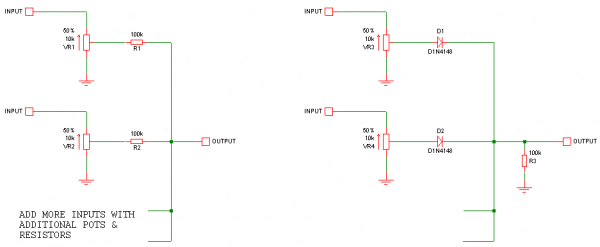
I said why I made those changes in my above post, but I can go into more detail. It is standard practice to make pots into voltage dividers for mixers, however look at the connections of the heterodyne space explorer mixer. The bottom half of ALL the pots are effectively in parallel, and if you turn one all the way up and one all the way down, there will be a short to ground and things will release the magic blue smoke.
If you add resistors on the wipers of all the pots those problems are avoided, that's standard practice for mixing voltages together.
You may want a buffer for impedance matching, for example if you want to connect the mixer to something with low impedance, due to the maximum power transfer theorem... I'm sensing that may go over your head. some things for you to look up to help you understand this:
Voltage dividers
Resistors in series and parallel
Mixing voltages with resistors
Maximum power transfer theorem
Short circuits
Also try imagining the circuit with the pots in different positions, then follow connections around and you'll see that in some positions the outputs of some oscillators will be connected directly to ground.
You may need a cap on the output because most amplifiers are expecting AC signal inputs, without you have an oscillating, but DC, signal which could affect the amplifier circuitry badly and lead to unwanted distortion or malfunction.
_________________
As a mad scientist I am ruled by the dictum of science: "I could be wrong about this but lets find out"
Green Dungeon Alchemist Laboratories |
|
|
Back to top
|
|
|
Psyingo

Joined: Jun 11, 2009
Posts: 248
Location: Canada
|
| Posted: Fri Sep 21, 2012 7:56 pm Post subject:
|
|
|
| buildafriend wrote: | got bored, made a layout. etching will come next. if people want PCB's for the box I can have a limited run printed. I can also provide an etchable layout for those who are into that.
It's the heterodyne space explorer. its a 4 oscillator square wave generator with a sag option and a 2 different mixer filters. It also has a master volume. It sums in mono. ( sag option is wired off board, its easy )
http://www.beavisaudio.com/Projects/CMOS_Synthesizers/
If you guys see any mistakes in the layout feel free to point it out. I banged it out in about a half hour. |
whats up with the unrouted ground? |
|
|
Back to top
|
|
|
Psyingo
Joined: Jun 11, 2009
Posts: 248
Location: Canada
|
| Posted: Fri Sep 21, 2012 7:59 pm Post subject:
|
|
|
| JingleJoe wrote: |
You may need a cap on the output because most amplifiers are expecting AC signal inputs, without you have an oscillating, but DC, signal which could affect the amplifier circuitry badly and lead to unwanted distortion or malfunction. |
good practice. most amps, and lots of other audio circuits, if meant for ac, will usually have a cap on the input anyway. but it is good to have it on the outs of your equipment, when dealing with audio. |
|
|
Back to top
|
|
|
buildafriend
Joined: Jan 30, 2011
Posts: 47
Location: New Jersey, US
|
| Posted: Sat Sep 22, 2012 8:53 am Post subject:
|
|
|
| Psyingo wrote: | | buildafriend wrote: | got bored, made a layout. etching will come next. if people want PCB's for the box I can have a limited run printed. I can also provide an etchable layout for those who are into that.
It's the heterodyne space explorer. its a 4 oscillator square wave generator with a sag option and a 2 different mixer filters. It also has a master volume. It sums in mono. ( sag option is wired off board, its easy )
http://www.beavisaudio.com/Projects/CMOS_Synthesizers/
If you guys see any mistakes in the layout feel free to point it out. I banged it out in about a half hour. |
whats up with the unrouted ground? |
the yellow lines represent all grounds that will be bussed to a copper ground plane. The ground plane is not yet added to aid in the visual clarity of the layout. (if I had the grounds hooked up right now, it would be hard to see exactly what was up). Note that some things may look like they are going to ground right now when they are in fact not going to ground because the yellow lines are floating over certain pads in order to connect to the pads that are actually going to ground.
Thanks for the looking at this and clearing up my mistakes guys! I'll revise. soon. |
|
|
Back to top
|
|
|
buildafriend
Joined: Jan 30, 2011
Posts: 47
Location: New Jersey, US
|
| Posted: Sat Sep 22, 2012 8:55 am Post subject:
|
|
|
| JingleJoe wrote: | I said why I made those changes in my above post, but I can go into more detail. It is standard practice to make pots into voltage dividers for mixers, however look at the connections of the heterodyne space explorer mixer. The bottom half of ALL the pots are effectively in parallel, and if you turn one all the way up and one all the way down, there will be a short to ground and things will release the magic blue smoke.
If you add resistors on the wipers of all the pots those problems are avoided, that's standard practice for mixing voltages together.
You may want a buffer for impedance matching, for example if you want to connect the mixer to something with low impedance, due to the maximum power transfer theorem... I'm sensing that may go over your head. some things for you to look up to help you understand this:
Voltage dividers
Resistors in series and parallel
Mixing voltages with resistors
Maximum power transfer theorem
Short circuits
Also try imagining the circuit with the pots in different positions, then follow connections around and you'll see that in some positions the outputs of some oscillators will be connected directly to ground.
You may need a cap on the output because most amplifiers are expecting AC signal inputs, without you have an oscillating, but DC, signal which could affect the amplifier circuitry badly and lead to unwanted distortion or malfunction. |
You are the man. Thanks!!! |
|
|
Back to top
|
|
|
JingleJoe
Joined: Nov 10, 2011
Posts: 878
Location: Lancashire, England
Audio files: 14
|
| Posted: Sun Sep 23, 2012 2:00 am Post subject:
|
|
|
Mixing voltages with resistors can be very useful, as you can use different resistors to get different "weighting" of voltages. That just means that in a two input mixer with say, 100k and 47k input resistors, the voltage applied to the 47k resistor will have greater presence/be louder/have more ffect than the one applied to the 100k resistor. If my fuzzy maths is right then the voltage input at the 100k resistor will be about 1/3 of the total voltage at the output, 2/3 of it coming from the 47k input. See the ratios there? 100k is almost twice 47k, so the voltage applies to it will be cut down by about half in comparison to the 47k input.
Thus you can use this method with control voltages to get fine tuning and coarse tuning I am really rambling now but it's all relevant to mixers.
_________________
As a mad scientist I am ruled by the dictum of science: "I could be wrong about this but lets find out"
Green Dungeon Alchemist Laboratories |
|
|
Back to top
|
|
|
buildafriend
Joined: Jan 30, 2011
Posts: 47
Location: New Jersey, US
|
| Posted: Sun Sep 23, 2012 10:16 am Post subject:
|
|
|
I am a hobyist and electronics student. I have built A LOT of stuff but design is always an endeavor for me.
Don't feel like you're preaching my friend. If we lived close I am sure we would both be friends and mentors to each other. I love learning about all audio/small signal electronics.
This just made me realize that I should start going to DIY synthesizer events. I think I read about the electromusic festival on here a while back. I think its in the US |
|
|
Back to top
|
|
|
JingleJoe
Joined: Nov 10, 2011
Posts: 878
Location: Lancashire, England
Audio files: 14
|
| Posted: Sun Sep 23, 2012 11:43 am Post subject:
|
|
|
Fortunately for you, it is! Unfortunately for me, there isn't really anything like that here 
_________________
As a mad scientist I am ruled by the dictum of science: "I could be wrong about this but lets find out"
Green Dungeon Alchemist Laboratories |
|
|
Back to top
|
|
|
buildafriend
Joined: Jan 30, 2011
Posts: 47
Location: New Jersey, US
|
| Posted: Sun Sep 23, 2012 1:35 pm Post subject:
|
|
|
| well... I JUST MISSED IT! it was about 2-3 weeks ago. I'll be waiting another year. |
|
|
Back to top
|
|
|
|

 Forum index » DIY Hardware and Software » Circuit Bending