| Author |
Message |
isak

Joined: Dec 13, 2009
Posts: 847
Location: Israel
Audio files: 18
|
 Posted: Tue Dec 25, 2012 2:41 am Post subject: Posted: Tue Dec 25, 2012 2:41 am Post subject:
 15V wall wart power supply 15V wall wart power supply |
  |
|
Hi guys.
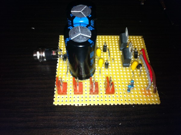
I stripboard the wall wart power supply from Ray's site and it's working great for -/+ 12V.
When trying to do the same for the 15V the (+) is ok, gives me 14.8V.
The (-) is giving me -17V.
I replaced the 7915 cause I thought it was bad, after replacing that it was the same results, (-)17V.
I wanted to build it again but before doing that I want to understand why it's putting out (-)17V?
Any ideas why?
This is the stripboard layout..

I thank you in advance,
Isak E.
_________________
http://www.myspace.com/mgmtrance
Last edited by isak on Tue Dec 25, 2012 8:24 am; edited 1 time in total |
|
|
Back to top
|
|
 |
Uncle Krunkus
Moderator

Joined: Jul 11, 2005
Posts: 4761
Location: Sydney, Australia
Audio files: 52
G2 patch files: 1
|
| Posted: Tue Dec 25, 2012 2:55 am Post subject:
|
|
|
I've had a pretty good look, and I can't see anything wrong with the stripboard layout. Which leads to the question, is your build exactly the same?
Also, you don't mention the voltage rating for the caps, this may need to go up. They all need at least 35V min.
_________________
What makes a space ours, is what we put there, and what we do there. |
|
|
Back to top
|
|
|
isak
Joined: Dec 13, 2009
Posts: 847
Location: Israel
Audio files: 18
|
| Posted: Tue Dec 25, 2012 3:18 am Post subject:
|
|
|
Hi uncle.
The caps are 50V
Tantalums 35V
And yes I did exactly as the layout shows.
I checked for shorts, I replaced the tantalums, replace the diods...and nothing!
Im driving my self crazy here, what could be wrong with such a simple board?
EDIT:
Another streang thing...
When taking the power plug off and keep on measuring with the multimeter the -17 goes down to -14.9V and stuck there for about 10 sec and only then discharges to 0.
_________________
http://www.myspace.com/mgmtrance |
|
|
Back to top
|
|
|
isak
Joined: Dec 13, 2009
Posts: 847
Location: Israel
Audio files: 18
|
| Posted: Tue Dec 25, 2012 5:18 am Post subject:
|
|
|
Do you think that I should add a trimmer to it?
If yes what would be the correct value?
I yes, should I add a resistor in series with it?
_________________
http://www.myspace.com/mgmtrance |
|
|
Back to top
|
|
|
isak
Joined: Dec 13, 2009
Posts: 847
Location: Israel
Audio files: 18
|
| Posted: Tue Dec 25, 2012 12:01 pm Post subject:
|
|
|
New findings...
I pul out the regulators from my good working -/+ 12V and replaced them to 7815 and 7915.
Guess what was the results?
The same!
It gives me +14.8V and -17V.
that's it I run out of ideas 
_________________
http://www.myspace.com/mgmtrance |
|
|
Back to top
|
|
|
isak
Joined: Dec 13, 2009
Posts: 847
Location: Israel
Audio files: 18
|
|
|
Back to top
|
|
|
Uncle Krunkus
Moderator
Joined: Jul 11, 2005
Posts: 4761
Location: Sydney, Australia
Audio files: 52
G2 patch files: 1
|
| Posted: Tue Dec 25, 2012 5:27 pm Post subject:
|
|
|
| isak wrote: | Another streang thing...
When taking the power plug off and keep on measuring with the multimeter the -17 goes down to -14.9V and stuck there for about 10 sec and only then discharges to 0. |
It could have something to do with the half wave rectification going to each rail. Center tapped transformer designs send a rectified ful wave to each rail. This one sends all the positive going pulses to the +ve side and the -ve ones to the -ve rail, but there's a space inbetween each rectified pulse, as the wave swings the other way. During this time, it's up to the ripple caps to supply the "gap". Now,... if there is no load, then the cap will not be completely (or possibly even partially) discharged when it recieves it's next pulse. So maybe there is a tiny transistion time when the regulator lets the cap plus the incoming transient through. Averaged out, this could read as higher (or lower) than the 15V you want.
This hypothetical effect may actually be exagerated by the diodes, which potentially provide paths for very fast transients caused by the back EMF of the transformer windings.
I would almost bet that (with no load) the -17V effect could be improved by using faster diodes. Not sure what type (or even if they exist as higher current rectifier types), but that's my theory.
_________________
What makes a space ours, is what we put there, and what we do there.
Last edited by Uncle Krunkus on Tue Dec 25, 2012 5:35 pm; edited 1 time in total |
|
|
Back to top
|
|
|
Uncle Krunkus
Moderator
Joined: Jul 11, 2005
Posts: 4761
Location: Sydney, Australia
Audio files: 52
G2 patch files: 1
|
| Posted: Tue Dec 25, 2012 5:33 pm Post subject:
|
|
|
BTW,
(without your added load resistors) does it read -17V with a module attached?
Keep in mind that this may just be a standard behaviour of this type of PSU when it's not under load, and probably just a trade off of using this type of design. Ray designs things very well, but he often does things to help the cost factor for experimenters. A more advanced PSU will no doubt overcome such drawbacks, but at an increased cost.
_________________
What makes a space ours, is what we put there, and what we do there. |
|
|
Back to top
|
|
|
elmegil

Joined: Mar 20, 2012
Posts: 2177
Location: Chicago
Audio files: 16
|
| Posted: Tue Dec 25, 2012 9:37 pm Post subject:
|
|
|
| Yah, Ray was commenting that the 7900's generally won't read correctly with no load....not sure about the difference between the 7912 and the 7915 |
|
|
Back to top
|
|
|
isak
Joined: Dec 13, 2009
Posts: 847
Location: Israel
Audio files: 18
|
| Posted: Wed Dec 26, 2012 12:02 am Post subject:
|
|
|
Thank you for the inputs guys.
Uncle,
To your question...
Well I didn't test it without the load resistor cause I was afraid that I will burn the module (IC's etc).
I test the module with the load resistors and it gave me the same read, +14.8V and -14.9V.
For the experiment matter do you think I should test it with no loads resistors?
Is it safe with -17V?
| Quote: | | advanced PSU will no doubt overcome such drawbacks, but at an increased cost. |
can you recommend on a good psu project?
i tell you why i'm asking, i building a synth and spend a lot of money already on components so another dollar or 2 for my self quite mind i rather spend on a good psu.
_________________
http://www.myspace.com/mgmtrance |
|
|
Back to top
|
|
|
Uncle Krunkus
Moderator
Joined: Jul 11, 2005
Posts: 4761
Location: Sydney, Australia
Audio files: 52
G2 patch files: 1
|
| Posted: Wed Dec 26, 2012 2:11 pm Post subject:
|
|
|
I doubt that anything which is expecting -15V (pretty much as to be an op-amp) will suddenly go belly up at -17V. And you've already shown that as soon as it has a load, it reads -15V anyway. I'd definitely give it a go.
As far as a better PSU goes, there are a few options. Of course you can buy ready built linear PSUs specifically for analogue synth systems, check the net for them.
If you're comfortable (and respectful  ) working with mains power. There are also heaps of DIY options. ) working with mains power. There are also heaps of DIY options.
I built a +/-15V precision PSU which I documented in another thread. I'll find a link for it and add it soon.
_________________
What makes a space ours, is what we put there, and what we do there. |
|
|
Back to top
|
|
|
isak
Joined: Dec 13, 2009
Posts: 847
Location: Israel
Audio files: 18
|
|
|
Back to top
|
|
|
Uncle Krunkus
Moderator
Joined: Jul 11, 2005
Posts: 4761
Location: Sydney, Australia
Audio files: 52
G2 patch files: 1
|
|
|
Back to top
|
|
|
isak
Joined: Dec 13, 2009
Posts: 847
Location: Israel
Audio files: 18
|
| Posted: Thu Dec 27, 2012 2:06 am Post subject:
|
|
|
Thank for the link.
It's looks beauty project, well done!
I think it's to advaced for me
I don't want to play with V to much.
_________________
http://www.myspace.com/mgmtrance |
|
|
Back to top
|
|
|
|

 Forum index » DIY Hardware and Software » MusicFromOuterSpace.com designs by Ray Wilson