| Author |
Message |
Tony Deff
Joined: May 25, 2008
Posts: 51
Location: Suffolk, UK
|
 Posted: Sat Aug 25, 2012 4:55 am Post subject:
Programmable Divider with Pseudo-Square output Posted: Sat Aug 25, 2012 4:55 am Post subject:
Programmable Divider with Pseudo-Square output
Subject description: 9-bit switch-programmable division retains duty cycle ≈ 50%. Top-Octave Generator note replacement |
  |
|
If you inter-connect three '163-type counters in the quirky configuration shown here, then you have a switch-programmable divider with an output that is always either a square-wave (even divisors), else a pseudo-square-wave (switch S1 closed for odd divisors).
Achieving this result is harder than it sounds, and exploits the exclusive dual enables of the 74HC163 plus its almost-unique synchronous load together with a highly unorthodox connection scheme, used to overcome problems often encountered with stand-alone programmable dividers, viz.:
Pulse or spike output.
Switch setting n may equate to divisor (n+1) etc.
Extra “glue-logic” required.
Operational frequency must be doubled in order to derive square output.
The operation of the circuit is not easy to understand (and even its designer got confused more than once!) and although it was rejected by Elektor as being “too simple for our readers”, there is not much point trying to understand how it works unless you need to keep your brain active. The simplest way of explaining it is that IC1 & IC2 count half-periods (first the Space, then the Mark) so that switches S2 – S9 assume double their usual binary value (“weightings”). IC3 functions as timing control and output toggle stage. With S1 closed (on), an extra clock period delay is injected into the output “space” (i.e. IC3/Qd = LOW) period.
With all 9 switches closed (divide-by-511), the output mark-space ratio is 255:256.
A limitation to “what-you-see-on-the-switches-is-what-you-get”, is that the minimum divisor is 6, even if the switches are all set open/off (value = zero).
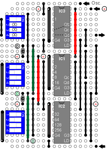
To prove the design as quickly as possible, the prototype used 4-way switch-banks suited to the data inputs of the ’163N. The switches are sandwiched between a 10K pull-up SIL pack and a 220R pull-down (inverted, pin 1 to ground). These can be found on the surplus market (in various lengths) remarkably cheap and make a quick, neat job of wiring the switches to pseudo-ground.
The strip-board track is left uncut at all pin 16s and at IC1 pin 7, and at IC3 pin 6 (including underneath pin 8 of the unused switch). (You may also wish to limit track-cutting under IC3 so as to allow a link from pin 13 to pin 5).
This layout is unsatisfactory in that three out of four switches in one switch-bank are un-used. It would be more aesthetic to use a 10-way switch-bank, perhaps aligning switches 2 - 5 against IC1 pins 3 - 6.
Free with every viewing! Application Note: Guitar "Pitch-Pipe"
Input = 153.6kHz. (e.g from pin 7 of a 74HC4060 running with a 2.4576 MHz. xtal)
1 2 3 4 5 6 7 8 9
_ ¯ ¯ _ ¯ _ _ _ ¯ E (= /233) → 659.2 Hz.
_ _ _ ¯ _ _ ¯ ¯ _ B (= /311) → 493.9 Hz.
_ ¯ _ _ _ ¯ _ ¯ _ G (= /392) → 391.8 Hz. [0.7 cent flat]
With input one octave lower (pin 5 of 74HC4060)
1 2 3 4 5 6 7 8 9
_ ¯ ¯ _ ¯ ¯ ¯ _ _ A (= /349) → 220.1 Hz. [0.45 cent sharp]
¯ _ ¯ ¯ _ ¯ _ _ _ E (= /466) → 164.8 Hz.
| Description: |
| This layout is convenient in matching the switches to the counter inputs but is unsatisfactory in the isolated position of the odd/even (value = 1) switch, S1, and the 3 switches which have no function. |
|
| Filesize: |
25.7 KB |
| Viewed: |
6476 Time(s) |

|
| Description: |
| Showing switch settings to divide 4.19403MHz. by 501 to generate a Top-C pseudo-square-wave. |
|
| Filesize: |
21.69 KB |
| Viewed: |
416 Time(s) |
| This image has been reduced to fit the page. Click on it to enlarge. |

|
Last edited by Tony Deff on Fri Feb 01, 2013 10:58 am; edited 1 time in total |
|
|
Back to top
|
|
 |
Tony Deff
Joined: May 25, 2008
Posts: 51
Location: Suffolk, UK
|
 Posted: Thu Jan 31, 2013 6:19 am Post subject:
Replacing an output from a Top-Octave Generator Posted: Thu Jan 31, 2013 6:19 am Post subject:
Replacing an output from a Top-Octave Generator
Subject description: How to configure the HC163 "overflow-mode" counter |
  |
|
Generating a square-wave from an even divisor is trivial, but if you need to replace an odd-divisor output from a Top-Octave ASIC (Application-Specific IC, such as the pre-historic MO83, MO87, TMS3617, MK50240 or AY-1-0212), then a pseudo-square output is essential — unless you can double the oscillator frequency and hope any CMOS dividers are able to cope, else make-do with an output an octave lower.
If your interest in the above (switchable) divider was for such a purpose, then what settings you need for which divisor is unimportant and the circuit can be simplified.
Extra bits can then be allocated to the main counter (11-bit division), or used as auxiliary octave dividers.
The 8-3 overflow counter† configuration shown below covers the common 9-bit TOGware† set 239 – 415.
Dr. David Ryder (who contributed much to electronic organ design), writing in Electronic Organ Magazine in 1983 (the in-house publication of
The Electronic Organ Constructors Society ) called this the Stapelfeld 9-bit series.
The example below will be configured to replace a divide-by-301 (which gives a surprisingly accurate Ab from a 2.0 / 4.0 MHz crystal reference).
Those black things are SIL (Single-In-Line) resistor packs of non-critical value, to be found cheap on the surplus market in various lengths.
If you use one of 7 or 8 pins, then IC1 is automatically enabled (by pulling pins 7 & 10 high).
When you build this circuit on a piece of virginal copper-strip board, the output mark:space is 256:257 (i.e. divide-by-513).
Lesser divisors (in quantum multiples of 4) are obtained by using a track-cutter (or drill bit) between the input/output pins of IC1 and IC2.
The pull-up resistors then come into play.
By cutting the track between IC1 pins 4 and 13, the output is reduced by 4 (to divide-by-509, the mark:space being reduced equally to 254:255).
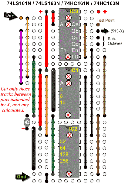
To reduce the counter from divide-by-513 to divide-by-301, it is necessary to cut alongside those pins marked:
301 = 513 -128 -64 -16 -4 [derivation of top Ab from 4.0 MHz by cutting four of seven tracks]
Once the copper tracks are broken, "repair" is made by linking inputs to ground, as required to increase the output from the minimum count.
The minimum count is 5 with the feedback link shown, or 4 if the feedback link is removed (when implementing even divisors).
This minimum figure is an "overhead" which comes from the circuit operation. For the moment, consider it as a supermarket deal, "divide-by-296, get 5 free!"
301 = 256 + 32 +8 +5 (free bonus) [same derivation of Ab from 4.0 MHz, but calculated as linking three of seven pullups to ground]
501 = 513 - 8 - 4 [deriving top C from 4.194304 MHz by cutting two tracks]
501 = 256 + 128 +64 + 32 + 16 [deriving top C from 4.194304 MHz by adding 5 links to ground]
†8-3 overflow counter : To be explained in a later posting — things are technical enough for the moment!.
†TOGware: a term coined to mean the set of 12 integers used by hardware, firmware or software to gemerate a digital top octave.
TOG is the UK abbreviation for Top Octave Generator, known for some inexplicable reason as a Top Octave Synthesiser in the U.S.
(A prize for anyone who can explain the difference between a top octave and a synthesised top octave).
| Description: |
| Layout for 9-bit division with simple digital feedback. |
|
| Filesize: |
50.77 KB |
| Viewed: |
222 Time(s) |
| This image has been reduced to fit the page. Click on it to enlarge. |

|
|
|
|
Back to top
|
|
 |
Tony Deff
Joined: May 25, 2008
Posts: 51
Location: Suffolk, UK
|
 Posted: Sun Feb 03, 2013 8:48 am Post subject:
High-resolution Digital Top-Octaves Posted: Sun Feb 03, 2013 8:48 am Post subject:
High-resolution Digital Top-Octaves
Subject description: 10-bit (11 and 12-bit) division |
  |
|
The following example demonstrates two small modifications required to deal with divide-by-959.
As before, the counters cascade in conventional synchronous manner: the carry output from IC1 (pin 15) feeds the two enables (pins 7 & 10) of IC2.
When IC1 & IC2 are "full-up" (=255), IC3 is enabled (via IC2, pin 15).
On the next rising edge of the common clock, IC3 increments whilst IC1 & IC2 "roll-over" to zero.
As long as our test point ("registered overflow" ) remains high, all is conventional and, according to the Texas data (1988), this simple cascade should be good for 14MHz.
To implement dividers from TOGware set 508, 538 ... 959, the previous layout is reconfigured as a 9 + 2 overflow counter, giving effective 10-bit division at system output IC3 Qc. Comparing with the previous layout, notice that the allocation of IC3 inputs/outputs has "slipped down a notch", leaving input A as the new most significant input.
The additional bit can boost maximum division to 1025 (513 + 512 ).
Just one sub-octave is now available — this can be similarly dispensed with should you need 11-bit division.
The simplicity of the previous feedback may have blinded you from noticing that 50% of odd divisors are not implementable with that circuit.
Consider trying to implement divide-by-239 by the method given: 239 = 513 - 256 - 16 - 2
As with divide-by-959 (= 1025 - 64 - 2), half of all odd numbers incorporate a binary bit value ("weighting") of 2, which previously did not warrant a mention.
If an inverter is available, or you can spare a couple of counter bits as here, then you can set any mark-space ratio that takes your fancy. If, however, you need all your counter bits and do not want to tack-on an inverter, taking the feedback to both inputs A and B reduces any count by 2, because (at the end of every mark period) input B is is being pre-set 2 counts nearer to the counter's maximum. The minimum divisor is now (2:5) and the maximum count is 1023 (= 510:513).
Now, we can achieve 959 as 959 = 1023 - 64 (i.e simply cutting the track between IC2 pins 4–13). The mark-space ratio of 478:481 will not be obvious.
Similarly, we can now achieve 239 as 239 = 511 - 256 - 16. (Mark-space ratio 118:121).
| Description: |
| Complete top-octave build data |
|
| Filesize: |
24.07 KB |
| Viewed: |
6043 Time(s) |

|
| Description: |
| A top C# pseudo-square-wave from 4.2525MHz |
|
| Filesize: |
74.02 KB |
| Viewed: |
240 Time(s) |
| This image has been reduced to fit the page. Click on it to enlarge. |

|
|
|
|
Back to top
|
|
 |
|

