| Author |
Message |
-minus-
Joined: Oct 26, 2008
Posts: 787
Audio files: 13
|
 Posted: Mon Nov 11, 2013 9:20 am Post subject:
Superseque Up/Down counting problem Posted: Mon Nov 11, 2013 9:20 am Post subject:
Superseque Up/Down counting problem
Subject description: Any advice please? |
  |
|
Hi,
I have been working on the Thomas Henry Superseque I found here:
http://machines.hyperreal.org/categories/DIY/sequencer/supseq.pdf
I thought I had this working on breadboard, but now I have stripboarded it, I have run into a problem.
I understand the length of the sequence is set by patching a cable between a gate output and the LENGTH input socket. So for example, if a sequence of 6 steps is required, patching from GATE 6 output to the LENGTH input will run the sequence 1, 2, 3, 4, 5, 6, then back to 1.
This works fine in the UP count mode. When I switch S4 to the Up/Down mode, strange things happen. It counts 1 to 6 but then also counts one step further to 7, before reversing.
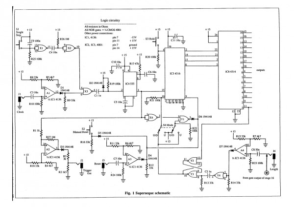
I suspect the problem is in the bottom right of the schematic on page 2 of the above link. There is something not quite right with X4, Y1, Y2, Y3, Y4 and the associated wiring. I have checked the switch wiring (which along with pots), I always get wrong. It seems correct. Something is not inverting somewhere perhaps? I have been stuck on this for a couple of days. Any advice or help is much appreciated! |
|
|
Back to top
|
|
 |
-minus-
Joined: Oct 26, 2008
Posts: 787
Audio files: 13
|
| Posted: Mon Nov 11, 2013 11:52 am Post subject:
|
|
|
I think I've isolated the problem to between the LENGTH input circuitry and the flip-flop.
If I take a gate output from a step and instead of plugging into the LENGTH input, I go directly to the flip-flop at pin 8 of Y3, it counts UP and DOWN as it should. Working back from pin 8 of Y3 towards the LENGTH input socket, the problem of the extra step occurs at Y4 pin 5 and 6 tied to invert the signal.
Thomas mentions in his text: "The output of comparator A4 is inverted by Y4, and the signal is capacitively coupled via C2 to the flip-flop's reset input. Capacitive coupling is used here since various timing considerations dictate that the flip-flop respond to an edge, not a level."
Something is not right here. I guess I don't understand the need for the inverted signal or how C2 works. 
I could just bypass that inverter, but when I read "Capacitive coupling is used here since various timing considerations dictate that the flip-flop respond to an edge, not a level", I get a bit worried. What are the various timing considerations? I don't want to get a rude surprise later.
I'm running this on 12V not 15V but I'm not sure it would make a difference. Is it maybe that capacitor value, C2, which I should experiment with?
I'm so close to having this working. I just need to figure out this UP DOWN count issue...
| Description: |
|
| Filesize: |
336.02 KB |
| Viewed: |
323 Time(s) |
| This image has been reduced to fit the page. Click on it to enlarge. |
|
|
|
|
Back to top
|
|
|
varice

Joined: Dec 29, 2004
Posts: 961
Location: Northeastern shore of Toledo Bend
Audio files: 29
G2 patch files: 54
|
| Posted: Mon Nov 11, 2013 2:08 pm Post subject:
|
|
|
Using +12 volts instead of +15 will cause the reference voltage at pin 6 of A4 to be lower than normal.
Could you temporarily use +15 volts to see if that corrects the up/down function? If not, maybe put a 100K resistor in parallel with R15 to bring the reference voltage up a bit.
BTW, the other three opamps also use reference voltages that are affected by using other than a +15 volt supply, although the function of A4 is going to be more sensitive to this supply change.
_________________
varice |
|
|
Back to top
|
|
|
gdavis
Joined: Feb 27, 2013
Posts: 359
Location: San Diego
Audio files: 1
|
| Posted: Mon Nov 11, 2013 3:22 pm Post subject:
|
|
|
| -minus- wrote: | I think I've isolated the problem to between the LENGTH input circuitry and the flip-flop.
If I take a gate output from a step and instead of plugging into the LENGTH input, I go directly to the flip-flop at pin 8 of Y3, it counts UP and DOWN as it should. Working back from pin 8 of Y3 towards the LENGTH input socket, the problem of the extra step occurs at Y4 pin 5 and 6 tied to invert the signal.
Thomas mentions in his text: "The output of comparator A4 is inverted by Y4, and the signal is capacitively coupled via C2 to the flip-flop's reset input. Capacitive coupling is used here since various timing considerations dictate that the flip-flop respond to an edge, not a level."
Something is not right here. I guess I don't understand the need for the inverted signal or how C2 works.
I could just bypass that inverter, but when I read "Capacitive coupling is used here since various timing considerations dictate that the flip-flop respond to an edge, not a level", I get a bit worried. What are the various timing considerations? I don't want to get a rude surprise later.
|
Looks to me like the timing issue arises in up mode. The cross-coupled NOR's Y2 and Y3 form an SR latch. A high signal on the length input results in the counter being reset which drives the other input of the SR latch high. Without the capacitor, this could lead to a situation where both S and R are high at the same time which is an invalid state. I suspect the cap is there to make S a quick pulse to avoid both S and R being high at the same time.
With the way the comparator is setup I don't really know why the inverter and C2 would be necessary though.
Does the problem occur only with higher clock rates or also with slow clock rate or manual stepping?
_________________
My synth build blog: http://gndsynth.blogspot.com/ |
|
|
Back to top
|
|
|
-minus-
Joined: Oct 26, 2008
Posts: 787
Audio files: 13
|
| Posted: Mon Nov 11, 2013 4:02 pm Post subject:
|
|
|
Thanks for your reply. I tried what you have suggested but is doesn't seem to make a difference. I do understand what you are getting at though.
A 100K in parallel with the 33K would be 24.812K. This would give a reference voltage of 1.965V using a 12V supply. At 15V the reference voltage is 1.87V. I've used an online calculator to come up with these figures.
It's strange I did not pick this problem up on the breadboard. I've gone over the stripboard layout and the actual board and can't see anything obviously wrong.
The only other thing it may be is I substituted a TL074 for the 4136. The pinout was different but I corrected that. Do you think this may be an issue? |
|
|
Back to top
|
|
|
-minus-
Joined: Oct 26, 2008
Posts: 787
Audio files: 13
|
| Posted: Mon Nov 11, 2013 4:23 pm Post subject:
|
|
|
| gdavis wrote: | With the way the comparator is setup I don't really know why the inverter and C2 would be necessary though.
Does the problem occur only with higher clock rates or also with slow clock rate or manual stepping? |
The problem occurs regardless of clock rate.
I have bypassed the inverter and C2 and it does solve the problem in UP/DOWN mode. If I patch step six gate to the LENGTH input, it counts 1, 2, 3, 4, 5, 6, 5, 4, 3, 2, 1, 2, etc as it should. Gone is the mysterious extra step before it reverses. However, if I switch to UP mode, it will only count 5 steps and reset. So I solve one problem and create another.
Thomas states on page 3 and 4 of the article:
"With S4 in the up mode position, pin 10 of the 4516 is pulled high, and this guarantees that the counter will count only in the up direction. Notice too that the flip-flop is now coupled to the reset pin of IC5, at pin 9. You shouldn't have too much trouble convincing yourself that the counter will now count up until it hits the highest stage, then resets to stage one and restarts over again. Incidentally, by using the flip-flop composed of Y2 and Y3, and making the reset input edge sensitive, any unusual timing anomalies are completely avoided. Every stage is on for an equal amount of time since the reset signal is recognized only at the time of the NEXT clock pulse. This is a small, but important, point and took over half the design time to work out."
See, this is the bit which is taking me half the time to work out  . .
There is something wrong with what I have done here. I have alligator clipped a LED to the output of pin 10, the flip-flop. This is confirming that the length section is flipping the flip-flop at least. So I am patching a lead from gate 6 and at the end of the step 6 gate cycle, on the falling edge of gate 6, I am getting the LED (EDIT: Go OFF) at pin 10 of Y3.
And... (EDIT again), I am noticing the LED come on at the flip-flop output (pin 10) as soon as step 1 comes ON on the downwards count. Obviously this is different to what is happening to the upwards count when it should reverse.
Last edited by -minus- on Mon Nov 11, 2013 4:40 pm; edited 1 time in total |
|
|
Back to top
|
|
|
gdavis
Joined: Feb 27, 2013
Posts: 359
Location: San Diego
Audio files: 1
|
| Posted: Mon Nov 11, 2013 4:38 pm Post subject:
|
|
|
I've been staring at the schematic thinking man, half this thing is to avoid the reset timing issue!
Still trying to wrap my head around it, seems like kind of an odd solution but nothing I can think of explains the issue you're having. The TL074 has a higher slew rate which might be affecting things, but again, I couldn't explain why it would at this point.
_________________
My synth build blog: http://gndsynth.blogspot.com/ |
|
|
Back to top
|
|
|
-minus-
Joined: Oct 26, 2008
Posts: 787
Audio files: 13
|
| Posted: Mon Nov 11, 2013 4:42 pm Post subject:
|
|
|
| Thanks for the reply. I appreciate it! I wasn't expecting any replies with a circuit so old now. It does seem to be a timing issue... |
|
|
Back to top
|
|
|
gdavis
Joined: Feb 27, 2013
Posts: 359
Location: San Diego
Audio files: 1
|
| Posted: Mon Nov 11, 2013 4:58 pm Post subject:
|
|
|
| -minus- wrote: | | Thanks for the reply. I appreciate it! I wasn't expecting any replies with a circuit so old now. It does seem to be a timing issue... |
Well I've never even seen the circuit before, I'm just looking at the schematic trying to see what could potentially cause the problem you're having. But it seems like if you were going to have a problem it would be with up mode. If up mode works, I can't see any reason why up/down would behave the way it is.
Shot in the dark: try a 4136 or equivalent if you can or decrease the value of C8.
_________________
My synth build blog: http://gndsynth.blogspot.com/ |
|
|
Back to top
|
|
|
-minus-
Joined: Oct 26, 2008
Posts: 787
Audio files: 13
|
| Posted: Mon Nov 11, 2013 5:12 pm Post subject:
|
|
|
When it is counting back down, pin 10 of the flip-flop goes high as soon as step on comes on. At the same time. The UP/DOWN counter, IC5, needs a + voltage on pin 10 to count in UP mode. This is there as soon as step 1 is engaged.
When it counts back up however, and it reaches the step patched to the LENGTH socket (in my case at present, step 6), the voltage is still high until step six is off, then it goes low. At this point it has advanced beyond step 6 and having now a low voltage on pin 7, it reverses and counts down to step one.
I guess what I need is for that flip-flop to go low at the beginning of the patched length step, not after it falls.
I've just seen 4136's on ebay. Maybe I'll have to get hold of some and try that if all else fails. It just means I'll have to make a mess of the board to allow for pinout differences. I'll see if I can sort this out over the next few days. Maybe I'll PM Thomas if I have no luck... |
|
|
Back to top
|
|
|
gdavis
Joined: Feb 27, 2013
Posts: 359
Location: San Diego
Audio files: 1
|
| Posted: Mon Nov 11, 2013 5:29 pm Post subject:
|
|
|
Maybe too obvious, but are you sure you connected the step outputs correctly? Sounds like you have have shifted it at some point (the dreaded "off by one" error)? It can be confusing because the steps are numbered 1-16, but the 4514 outputs are labeled S0-S15. so S5 would be step 6 and S6 would be step 7. Maybe you wired step 6 to S6?
_________________
My synth build blog: http://gndsynth.blogspot.com/ |
|
|
Back to top
|
|
|
-minus-
Joined: Oct 26, 2008
Posts: 787
Audio files: 13
|
| Posted: Mon Nov 11, 2013 5:35 pm Post subject:
|
|
|
I wouldn't put it past me doing that. This circuit has been depriving me of sleep, as is often the case. I'll check that now. I'm pretty sure I religiously followed the diagram though.
The wiring appears to be correct. I might clear some space and try to get the breadboard version hooked up again. Maybe that will reveal something, or perhaps not.  |
|
|
Back to top
|
|
|
-minus-
Joined: Oct 26, 2008
Posts: 787
Audio files: 13
|
| Posted: Mon Nov 11, 2013 6:14 pm Post subject:
|
|
|
OK! Bit too early to call it, but I just ripped out the TL074 and replaced it with a new one. It appears to be working! 
I'm going to solder the switch back as I removed it earlier when I thought I had that part wrong, but it is counting up and down as it should, and indeed up and resetting correctly.
So it was something simple!  Thanks for your time guys. I'll post a nice stripboard layout soon. Thanks for your time guys. I'll post a nice stripboard layout soon. |
|
|
Back to top
|
|
|
|

 Forum index » DIY Hardware and Software » Thomas Henry designs
