| Author |
Message |
Vanwonky

Joined: Jul 24, 2013
Posts: 22
Location: Perth, Australia
|
 Posted: Thu May 22, 2014 7:35 am Post subject:
40106 oscillator module build - help please Posted: Thu May 22, 2014 7:35 am Post subject:
40106 oscillator module build - help please
Subject description: Can't get this working correctly |
  |
|
Howdy All,
I have been lurking (as a member) here for ages having a ball breadboarding all sorts of stuff and driving the family nuts with noises coming out of the office! Time has come to get my Lunetta synth actually made but this module is driving me nuts.
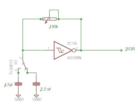
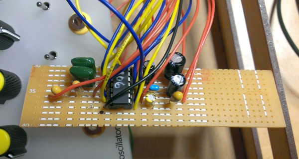
Just a 40106 using all six in/outs. 4 have switchable caps for a bit of variation. I have some big caps in there (330μF is the largest) since I want some really slow clock timing for some and up to 1μF and above that and the green I don't even know the value of but sound good. I am using the circuit below on the 4 with switches and just straight on the other two. I didn't breadboard this with switches I will admit. Something is very wrong though. For starters if the voltage is at 9 volts it will oscillate for a few seconds then stop. If I take the voltage to around 8 and even down to 5 volts it works sort of right but the sound is still a bit wonky.
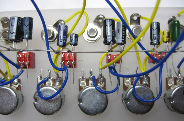
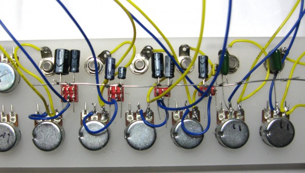
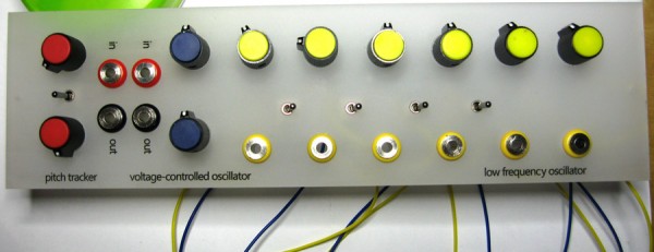
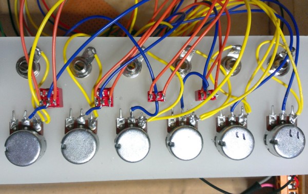
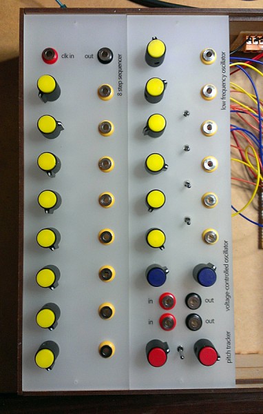
As far as I can tell the wiring seems correct but I am missing something fundamental here. I have attached a couple of images of the module wiring and front.
Please note that the image doesn't show my connection to ground on the negative rail for the caps as I used a crocodile lead whilst testing.
Yellow wires are outputs. Blue are inputs.
Hope someone can help. I have spent hours trying to fault find this with different wiring arrangements and caps. Please let me know if you need more info.
Cheers
Dave
| Description: |
|
| Filesize: |
21.53 KB |
| Viewed: |
9016 Time(s) |
|
| Description: |
|
| Filesize: |
159.08 KB |
| Viewed: |
196 Time(s) |
| This image has been reduced to fit the page. Click on it to enlarge. |
|
| Description: |
|
| Filesize: |
164.77 KB |
| Viewed: |
217 Time(s) |
| This image has been reduced to fit the page. Click on it to enlarge. |
|
| Description: |
|
| Filesize: |
73.47 KB |
| Viewed: |
202 Time(s) |
| This image has been reduced to fit the page. Click on it to enlarge. |
|
|
|
|
Back to top
|
|
 |
PHOBoS

Joined: Jan 14, 2010
Posts: 5617
Location: Moon Base
Audio files: 705
|
|
|
Back to top
|
|
|
blue hell
Site Admin

Joined: Apr 03, 2004
Posts: 24088
Location: The Netherlands, Enschede
Audio files: 278
G2 patch files: 320
|
| Posted: Thu May 22, 2014 9:18 am Post subject:
|
|
|
Large electrolytics can be a problem in this circuit as the leakage current of the caps will be in about the same range as the minimum current flowing through the pot .. this may stop oscillations.
However I' d expect that effect to be worse on lower supply voltages.
Yup, very nice panel!
_________________
Jan
also .. could someone please turn down the thermostat a bit.
 |
|
|
Back to top
|
|
|
elektrouwe
Joined: May 27, 2012
Posts: 143
Location: Germany
|
| Posted: Thu May 22, 2014 11:39 am Post subject:
|
|
|
| Blue Hell wrote: | Large electrolytics can be a problem...
However I' d expect that effect to be worse on lower supply voltages.
... |
I also guess that 's the problem. And it is worse with higher operating voltage, because the average cap voltage ( around V/2 ) causes a higher leakage current through the caps then. So the behavior matches theory 
you can try to cure the bad cap behavior : take them out and attach them
to a power supply with the rated cap voltage for some minutes. Don't forget
to discharge them before resoldering them into your Lunetta !
Another option: compensate the leakage current by wiring a 22k..100k resistor from the caps to +9V.
BTW: I'd rather use small non-electrolyte Cs and use a 4040 to get the low freqs. |
|
|
Back to top
|
|
|
Vanwonky
Joined: Jul 24, 2013
Posts: 22
Location: Perth, Australia
|
| Posted: Thu May 22, 2014 5:00 pm Post subject:
|
|
|
PHOBoS - Thanks for the welcome. After the dodgy behaviour on stripboard I went back to breadboard so I can take a pic of that later but really it is just the in/out into the 40106 plus power. I stripped the board of all other parts to make sure they aren't causing problems.
Blue Hell / elektrouwe - Yes the caps might be an issue to look at. I have had no problems using any of those caps breadboarded. I will try smaller values and then non-electrolyte. As you say elektrouwe a 4040 for the slow rates. But grrrr! This should work!
Thanks for the comments on the panel guys. Blinkys to come. The panel is 6mm satin perspex. The LEDs will sit just touching the back giving a funky glow if I get this thing working  |
|
|
Back to top
|
|
|
corex

Joined: Mar 02, 2010
Posts: 114
Location: Las Vegas
|
| Posted: Fri May 23, 2014 12:45 pm Post subject:
|
|
|
That's an interesting point about electrolytic leakage currents. I've noticed that 10uF electrolytic is about the biggest size I've been able to use (on +12V supply) but I was never sure why. I normally prefer to use 1uF film caps (just the biggest non-electrolytic I have).
But if you've tried it on breadboard with those caps, Vanwonky... weird. |
|
|
Back to top
|
|
|
Vanwonky
Joined: Jul 24, 2013
Posts: 22
Location: Perth, Australia
|
| Posted: Fri May 23, 2014 7:15 pm Post subject:
|
|
|
Yeah thanks Corex. I tried some smaller caps but still getting some unpredictably insane results from nothing to dodgy unsteady oscillations. I wonder if the freeform wiring has some anntenae effect (pardon my basic electronics)? Also I bought the pots from Futurlec for 55 cents (AUS) each which seemed dirt cheap. 100K but they vary anywhere from 89 - 110K! Maybe the contacts in them are crappy as well. Anyway - I think I might just get all the caps back onto the stripboard so I can just get this built. It means a few more wires to the switches etc. but so be it. Fingers crossed.
| corex wrote: | That's an interesting point about electrolytic leakage currents. I've noticed that 10uF electrolytic is about the biggest size I've been able to use (on +12V supply) but I was never sure why. I normally prefer to use 1uF film caps (just the biggest non-electrolytic I have).
But if you've tried it on breadboard with those caps, Vanwonky... weird. |
|
|
|
Back to top
|
|
|
blue hell
Site Admin
Joined: Apr 03, 2004
Posts: 24088
Location: The Netherlands, Enschede
Audio files: 278
G2 patch files: 320
|
| Posted: Sat May 24, 2014 3:58 am Post subject:
|
|
|
Well .. big ccaps .. the 330 µF you menetioned earlier might not work when it's very leaky .. but stuff around 10 µF should just work, if not the first one at least the 2nd one and all following ..
Anyway, not an empty battery eh?
_________________
Jan
also .. could someone please turn down the thermostat a bit.
|
|
|
Back to top
|
|
|
Vanwonky
Joined: Jul 24, 2013
Posts: 22
Location: Perth, Australia
|
| Posted: Sat May 24, 2014 6:04 am Post subject:
|
|
|
Jan - I am putting the big caps back in the drawer till another day! Tomorrow I will pull everthing apart and solder the caps (smaller ones  onto the stripboard. "Anyway, not an empty battery eh?" - are you actually asking me if I am using an old battery or is that an 'electronics' joke I don't know yet onto the stripboard. "Anyway, not an empty battery eh?" - are you actually asking me if I am using an old battery or is that an 'electronics' joke I don't know yet  ? Just in case let me tell you I am using a lab power supply. ? Just in case let me tell you I am using a lab power supply.
| Blue Hell wrote: | Well .. big ccaps .. the 330 µF you menetioned earlier might not work when it's very leaky .. but stuff around 10 µF should just work, if not the first one at least the 2nd one and all following ..
Anyway, not an empty battery eh? |
|
|
|
Back to top
|
|
|
blue hell
Site Admin
Joined: Apr 03, 2004
Posts: 24088
Location: The Netherlands, Enschede
Audio files: 278
G2 patch files: 320
|
| Posted: Sat May 24, 2014 6:21 am Post subject:
|
|
|
Power supply, ok, got it ... heh .. you would not be the first one to run into trouble on a battery assumed to be full ... so was just checking to make sure.
_________________
Jan
also .. could someone please turn down the thermostat a bit.
|
|
|
Back to top
|
|
|
DUBmatze

Joined: Feb 18, 2013
Posts: 150
Location: south Germaica (schwabilon)
|
| Posted: Sat May 24, 2014 7:21 am Post subject:
|
|
|
...so i keep asking dumb questions...
you double checked the ground connection of the 40106?
using a normal 330u cap shud work fine. i have a osc here (from a 4093) with a socket for the caps. I have tested 470u, 1000u and 2200u. the only differnce is i have a 1.1k resistor in series to the pot and iam running my lunetta stuff at 5V from a 7805.
the panel is looking nice. |
|
|
Back to top
|
|
|
Vanwonky
Joined: Jul 24, 2013
Posts: 22
Location: Perth, Australia
|
| Posted: Sat May 24, 2014 8:43 am Post subject:
|
|
|
Hey DUBmatze - as far as I am concerned there are no dumb questions! Yes I quadruple checked the ground and everything else. I tried a different breadboard, 3 power supplys including a 9 volt battery and 4 different 40106's with all the same results. Very weird. I will strip it down and check all the components. I checked for dry joints everywhere but they all seemed fine. Mysterious. 
| DUBmatze wrote: | ...so i keep asking dumb questions...
you double checked the ground connection of the 40106?
using a normal 330u cap shud work fine. i have a osc here (from a 4093) with a socket for the caps. I have tested 470u, 1000u and 2200u. the only differnce is i have a 1.1k resistor in series to the pot and iam running my lunetta stuff at 5V from a 7805.
the panel is looking nice. |
|
|
|
Back to top
|
|
|
Vanwonky
Joined: Jul 24, 2013
Posts: 22
Location: Perth, Australia
|
| Posted: Sun May 25, 2014 6:24 am Post subject:
|
|
|
OK - fixed and working beautifully . I wired all the caps to the stripboard. It meant 2 more wires to each switch which means wires everywhere but who cares - it works! Used the big caps again as well - down to 470µF and no problems. Wished I could work out why the original method didn't work but now I can move on - yeehaa! Thanks to you guys for trying to help. I will have plenty more questions as I go no doubt  . .
| Description: |
| LFO switch wiring reworked |
|
| Filesize: |
142.16 KB |
| Viewed: |
166 Time(s) |
| This image has been reduced to fit the page. Click on it to enlarge. |
|
| Description: |
|
| Filesize: |
142.03 KB |
| Viewed: |
153 Time(s) |
| This image has been reduced to fit the page. Click on it to enlarge. |
|
| Description: |
|
| Filesize: |
150.19 KB |
| Viewed: |
152 Time(s) |
| This image has been reduced to fit the page. Click on it to enlarge. |
|
|
|
|
Back to top
|
|
|
|

 Forum index » DIY Hardware and Software » Lunettas - circuits inspired by Stanley Lunetta


