| Author |
Message |
cbfishes
Joined: Mar 01, 2015
Posts: 24
Location: Alto, Michigan
|
 Posted: Sun Mar 01, 2015 10:21 am Post subject:
Newbie question: How to power everything? Posted: Sun Mar 01, 2015 10:21 am Post subject:
Newbie question: How to power everything?
Subject description: Very confused about how to distribute steady power to many devices |
  |
|
Hey everybody– I've been lurking for a while and gotten a great deal out of everything you share here! Thanks for putting it out there. Recently I've been trying to learn basic electronics so I can build things that make noise. As you can imagine, very often my search results take me here.
I started with an APC kit from Makershed, and once I made that (sort of) successfully I've been trying other things. I made a simple clock/pulse module following the littlebits "pulse" schematic. Incredibly excited that I actually made something! A few weeks ago schematics were a complete mystery. Now I can sort of understand them. Trying to learn more!
That said, I have ZERO background in electronics, I'm terrible at math, and my logic is seriously flawed. I've reached a point where I am completely stuck, and my reading and searches have confused me even more.
Here's my situation: I have an APC module (1x 556 chip, spitting out a tone) and a pulse module (1x 555 chip spitting out pulses) mounted in my amateurish rack. When I run them both off of batteries, they work great. But if I plug both into the same power source, they both receive less voltage.
I've been trying to understand why this is; I thought a power source always supplies the same amount of voltage no matter what the load is. I've done some experiments and found that even a battery with a single resistor seems to put out less voltage than without a resistor.
So here's my question, and please forgive my total newb-ness:
How can you possibly plug multiple devices into one power source and make sure they get a constant level of power? I've been searching through the forum but haven't been able to figure it out.
I suspect those "voltage regulators" I've been reading about play a part here, but perhaps I'm missing some fundamental basic understanding of electricity.
Sorry for the long first post; I really love this site and appreciate everybody sharing their expertise. I'm getting very excited about this DIY thing. Here is some of what I've been working on:
New 555-based pulse module: https://vine.co/v/O22pnQAWzpO
Trying to learn about CV: https://vine.co/v/O2X6pIJZH6n
Sending voltage from Max for Live into the APC: https://vine.co/v/O2e0J0VXxX1
Monotron + APC: https://vine.co/v/OQ3MF63I2hW
_________________
making stuff that makes sounds is awesome!
Music/fishing/adventures blog CB Fishes
music.chrisbeckstrom.com |
|
|
Back to top
|
|
 |
PHOBoS

Joined: Jan 14, 2010
Posts: 5873
Location: Moon Base
Audio files: 709
|
Posted: Sun Mar 01, 2015 1:02 pm Post subject:
Re: Newbie question: How to power everything?
Subject description: Very confused about how to distribute steady power to many devices |
|
|
 
| cbfishes wrote: | | I thought a power source always supplies the same amount of voltage no matter what the load is. |
For an ideal power source which has an internal resistance of 0 that would be the case,. unfortunately real ones aren't ideal.
(maybe that's also a good thing because shorting an ideal supply would amount in an infinitly high current)
| Quote: | | I've done some experiments and found that even a battery with a single resistor seems to put out less voltage than without a resistor. |
That's ohm's law: If there is a current flowing through a resistor there is a voltage across it, which you'll have to subtract from the supply voltage.
| Quote: | So here's my question, and please forgive my total newb-ness:
How can you possibly plug multiple devices into one power source and make sure they get a constant level of power? I've been searching through the forum but haven't been able to figure it out.
I suspect those "voltage regulators" I've been reading about play a part here, but perhaps I'm missing some fundamental basic understanding of electricity. |
Since powersupplies aren't ideal there will always be some drop in voltage, however if it is a capable of supplying
enough current this will be neglectable. And yes that's what the regulators come in handy for. They keep the voltage
at a constant level independent of the supplied current, at least up to a certain point and as long as it's less than
your powersupply can handle.
Standard batteries aren't really good at supplying short bursts of current which you will need with the 555 circuits.
However if you place a large capacitor (>1000uF) in parallel with the battery this might stabilize it enough since
capacitors are excellent in providing a lot of current in a short time.
_________________
"My perf, it's full of holes!"
http://phobos.000space.com/
SoundCloud BandCamp MixCloud Stickney Synthyards Captain Collider Twitch YouTube |
|
|
Back to top
|
|
|
cbfishes
Joined: Mar 01, 2015
Posts: 24
Location: Alto, Michigan
|
| Posted: Sun Mar 01, 2015 2:28 pm Post subject:
|
|
|
Thanks so much for your response! It really makes sense and clears some things up for me.
So, theoretically, let's say you have a single-module synth, a VCO generating a sine wave at 440Hz, which is being powered by a 12V wall wart.
If you were to add an additional VCO and plug it into the same 12V wall wart, it would eat up some voltage (Ohm's law, right?).
Wouldn't that mean the first VCO would suddenly receive less voltage, meaning the 440Hz might go flat?
I suppose if it does go flat, it won't go very flat (as you said "this will be negligible") and that's what the "fine" tune knob is for anyway...
I'll try sticking some caps between the power and the 555s– I think I actually understand the concept! Thanks so much for the welcome and the very clear explanation!
_________________
making stuff that makes sounds is awesome!
Music/fishing/adventures blog CB Fishes
music.chrisbeckstrom.com |
|
|
Back to top
|
|
|
PHOBoS
Joined: Jan 14, 2010
Posts: 5873
Location: Moon Base
Audio files: 709
|
| Posted: Sun Mar 01, 2015 3:04 pm Post subject:
|
|
|
Simply put everthing you add will have an influence on the supply, that's why you'll often see a lot of small capacitors (100nF)
and a couple of bigger ones in circuits placed in parallel with the supply. This is adding an extra buffer for every circuit
and isolates them from each other to some degree. Also every cable has some resistance (although low) this is why you'd want
to use seperate cables to power each circuit. And you'll have to use cables that have a very low resistance, so not too thin.
When using something as a VCO you'll definitly need a regulated supply and sometimes (like with the yusynth VCO)
there are even extra regulators on the VCO itself to keep it stable. With analog VCO's it's often temperature that
can affect the tuning and you will come across VCO's that use tempco resistors to counter this.
A good way to get started with electronics here on the forum is the lunetta section. There are some simple circuits and more
complex ones posted there and it's very useful to get the basics down. And a lot of fun to make some weird noises 
_________________
"My perf, it's full of holes!"
http://phobos.000space.com/
SoundCloud BandCamp MixCloud Stickney Synthyards Captain Collider Twitch YouTube |
|
|
Back to top
|
|
|
AlanP
Joined: Mar 11, 2014
Posts: 746
Location: New Zealand
Audio files: 41
|
| Posted: Sun Mar 01, 2015 9:49 pm Post subject:
|
|
|
From what I understand, a given power supply is capable of supplying X volts with a maximum of Y amps.
The closer the circuits powered by that supply get to the maximum current draw, the more unhappy the powersupply is, and the voltage supplied starts to sag from X volts to some lower value, and the voltage regulator will start heating up more than usual.
I'd trust PHOBoS before me, though! |
|
|
Back to top
|
|
|
PHOBoS
Joined: Jan 14, 2010
Posts: 5873
Location: Moon Base
Audio files: 709
|
| Posted: Mon Mar 02, 2015 6:05 am Post subject:
|
|
|
It depends a bit on your powersupply:
Batteries can be pretty stable voltage wise and something like a D-cell can provide some serious current too.
A standard 9V battery doesn't do that well when it comes to current which causes the voltage to drop but is ideal
for small portable circuits because of it's higher voltage and size/weight.
A simple unregulated supply (transformer + rectifier + capacitors) will have an output voltage that is very dependent
on the load. You often find this type in cheap wallwarts of which the output voltage is higher when nothing is connected than
what it is rated at. (a quick test with an unloaded 9V wallwart gives me 12.2V but I've seen much worse).
If you add a regulator it will do it's best to keep the output voltage at the same level no matter the load. However to do this
the input voltage needs to be higher than what you want your regulated voltage to be. So there is a voltage across the
regulator (Vin - Vout) and also a current (I) flowing through it. This means that the power dissipated by the regulator is ± (Vin-Vout) X I.
This power is turned into heat and that's why you'll need to add heatsinks for large currents. Standard 78xx regulators are protected
against overheating though so they do switch of at some point but they can get VERY hot before this happens.
Also the transformer itself is rated for a maximum current at which it can provide the specified output voltage. Go above this
and not only will the voltage drop too far but it can fry the transformer wiring itself. There's also something with core saturation
of which I don't know much about but toroids seem to perform better when it comes to this.
This is just for standard linear supplies with basic 78xx regulators. There are more efficient regulators and you can also use
a switched powersupply.
_________________
"My perf, it's full of holes!"
http://phobos.000space.com/
SoundCloud BandCamp MixCloud Stickney Synthyards Captain Collider Twitch YouTube |
|
|
Back to top
|
|
|
cbfishes
Joined: Mar 01, 2015
Posts: 24
Location: Alto, Michigan
|
| Posted: Fri Mar 06, 2015 9:22 am Post subject:
|
|
|
Thanks for the explanations and suggestions– I think I'm starting to understand.
I've been experimenting with using capacitors and a voltage regulator (I only have one, a 5V 78## model) to try and alleviate my voltage issues.
Here's what I did this morning:
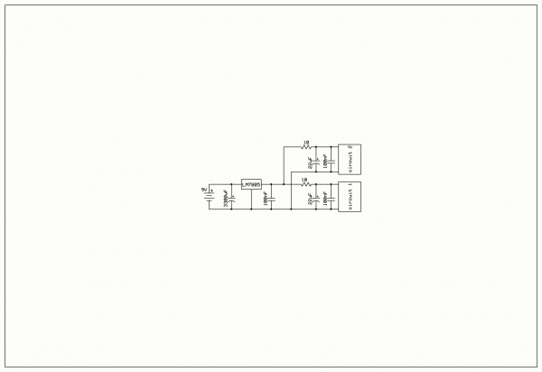
Instead of the 9V battery going directly into my 555 module and my op amp-based VCO, I put a bunch of capacitors in parallel (connecting + to -) and then a 5V voltage regulator. The power then connected to my 555 and VCO (see the schematic– I couldn't find a symbol for voltage regulator so I used a resistor).
The 555 is in astable mode so it's putting out pulses every few milliseconds (or seconds, depending on the potentiometers).
If the 555 is connected to an 8Ω speaker, the VCO saw wave stays constant (constant pitch).
If the 555 is NOT connected to an 8Ω speaker, the VCO saw wave varies along with the 555 (when the 555 is "on" the VCO gets less voltage).
On my multimeter I can watch what's happening; VCO only: 5 volts come out of the power. Add the 555: 5 volts when it isn't "on," then about 4 volts when it is on. As you can imagine this has quite an effect on the VCO.
Shouldn't the voltage regulator bump up the voltage back to 5V when the 555 gets hungry? There are 9V coming in so I'd think there is plenty of headroom... Maybe I don't understand how they work...
So... should I put parallel capacitors in the power supply as well as all my modules? How do I stop the 555 from sucking up so much voltage? A resistor between the supply and the 555 power input seems to help a little. Am I missing something here?
Right now I'm tempted to run everything on its own 9V battery, but I know that's not as practical (or eco-friendly) as running everything off a single supply.
Sorry to ask so many questions. I'm a real noob at this, and although I'm super excited to be making these sounds, I'm frustrated by these power issues.
| Description: |
|
| Filesize: |
18.53 KB |
| Viewed: |
184 Time(s) |
| This image has been reduced to fit the page. Click on it to enlarge. |
|
_________________
making stuff that makes sounds is awesome!
Music/fishing/adventures blog CB Fishes
music.chrisbeckstrom.com |
|
|
Back to top
|
|
|
piedwagtail

Joined: Apr 15, 2006
Posts: 297
Location: shoreditch
Audio files: 3
|
| Posted: Sat Mar 07, 2015 1:15 am Post subject:
|
|
|
Download a 7805 datasheet and peruse.
Note they insist on a capacitor to ground between the regulator and the load.
So on your diagram stick the regulator between your 1000uf caps.
Topics to research: impedance (regulator struggling with a low load impedance), reactance (of the capacitor), low pass filter (power supply filter capacitor).
Think about rivers, reservoirs , dams and household supply needs. |
|
|
Back to top
|
|
|
cbfishes
Joined: Mar 01, 2015
Posts: 24
Location: Alto, Michigan
|
| Posted: Sat Mar 07, 2015 3:48 am Post subject:
|
|
|
Awesome! Thanks for the hints. Data sheets! I'm starting to realize how important they are- it didn't even occur to me to look at the one for the regulator. Lesson learned!
I suspect part of my issue is I don't even really understand how electricity flows through a circuit, but learning this is part of why I'm doing this in the first place; to learn about circuits and make my own.
Thanks!
_________________
making stuff that makes sounds is awesome!
Music/fishing/adventures blog CB Fishes
music.chrisbeckstrom.com |
|
|
Back to top
|
|
|
JovianPyx

Joined: Nov 20, 2007
Posts: 1988
Location: West Red Spot, Jupiter
Audio files: 224
|
| Posted: Sun Mar 08, 2015 6:41 am Post subject:
|
|
|
| piedwagtail wrote: | Download a 7805 datasheet and peruse.
Note they insist on a capacitor to ground between the regulator and the load.
So on your diagram stick the regulator between your 1000uf caps.
Topics to research: impedance (regulator struggling with a low load impedance), reactance (of the capacitor), low pass filter (power supply filter capacitor).
Think about rivers, reservoirs , dams and household supply needs. |
As shown in the datasheets, the capacitor on the output of a 7805 regulator should be 0.1uF. If you place the regulator between the 1000 uF caps (as shown in the drawing), the capacitor on the 7805 regulator output will be 1000 uF which is way too large.
_________________
FPGA, dsPIC and Fatman Synth Stuff
Time flies like a banana.
Fruit flies when you're having fun.
BTW, Do these genes make my ass look fat?
corruptio optimi pessima
|
|
|
Back to top
|
|
|
piedwagtail
Joined: Apr 15, 2006
Posts: 297
Location: shoreditch
Audio files: 3
|
| Posted: Sun Mar 08, 2015 12:44 pm Post subject:
|
|
|
They do all the characteristic tests with 0.1uf, that I certainly concur with.
That is the minimum to keep stability.
Underlining words seems to have little to do with helping the original poster.
https://www.youtube.com/watch?v=b7UQVZaqxg0
is very informative for everyone. |
|
|
Back to top
|
|
|
JovianPyx
Joined: Nov 20, 2007
Posts: 1988
Location: West Red Spot, Jupiter
Audio files: 224
|
| Posted: Sun Mar 08, 2015 1:41 pm Post subject:
|
|
|
| piedwagtail wrote: | They do all the characteristic tests with 0.1uf, that I certainly concur with.
That is the minimum to keep stability.
Underlining words seems to have little to do with helping the original poster.
https://www.youtube.com/watch?v=b7UQVZaqxg0
is very informative for everyone. |
I've done the research and also have experience with these parts. The regulator is actually capable of fair stability without any capacitor on the output at all (this is clearly stated in more than one datasheet), however, they recommend the 0.1uF capacitor to reduce the RF effects of transient current requirements. Where the transient current requirements are large (200 mA step changes in current) a capacitor of 100 uF is suggested in at least one datasheet and not mentioned in others.
See this: http://forum.allaboutcircuits.com/attachments/lm340-7805-pdf.32522/ datasheet page 11. Note the diode across the input and output of the regulator to prevent damage from an input shorted to ground (remember - this is DIY). Here they describe the use of large capacitance on the output of the regulator. If the current transient's harmonic content is in the RF range, the smaller cap (100nF) does all the work to remove the RF (because electrolytics are very poor at doing that). Electrolytics are needed to mitigate large step changes in current which is probably not happening in the OP's circuit.
Not sure why you object to the underline, that was done for emphasis. Go look at other electronics forums (I have) and you'll see consensus that caps greater than 10 uF to 100 uF are considered overkill and are necessary only for specialized applications that produce large step changes in current - and then you need the protector diode across the input and output.
In my view, starting with 100 nF and then testing would determine whether an additional electrolytic is required.
_________________
FPGA, dsPIC and Fatman Synth Stuff
Time flies like a banana.
Fruit flies when you're having fun.
BTW, Do these genes make my ass look fat?
corruptio optimi pessima
|
|
|
Back to top
|
|
|
piedwagtail
Joined: Apr 15, 2006
Posts: 297
Location: shoreditch
Audio files: 3
|
| Posted: Sun Mar 08, 2015 5:39 pm Post subject:
|
|
|
Quoting from the above message:
| Quote: | | I've done the research and also have experience with these parts |
| Quote: | | Go look at other electronics forums (I have) |
I feel confident the casual reader can detect the implications JovianPyx wishes to make.
I'll PM the OP my further comments on this matter. |
|
|
Back to top
|
|
|
PHOBoS
Joined: Jan 14, 2010
Posts: 5873
Location: Moon Base
Audio files: 709
|
|
|
Back to top
|
|
|
JovianPyx
Joined: Nov 20, 2007
Posts: 1988
Location: West Red Spot, Jupiter
Audio files: 224
|
| Posted: Mon Mar 09, 2015 1:05 pm Post subject:
|
|
|
I did more research, looking at PSUs supplied by established commercial designers.
The schematics I looked at were all for analog synthesizer applications so that my findings would be relevant to this thread and my own needs as well.
The output depcoupling caps were quite consistent in that all included a 100nF cap in parallel with an electrolytic capacitor ranging from 1 uF to 47 uF, most in the lower end of that scale at 1uF to 10 uF. Some did not use an electrolytic at all but all included the 100 nF cap - the datasheets all mention that this cap is not absolutely necessary, but does enhance stability.
And all of the designs I looked at had the protection diode from regulator input to output for all PSU voltages. I also read that the problem of reverse discharge of an output decoupling electrolytic capacitor protects the regulator for more than just shorting the input to ground - apparently, simply powering down the circuit can cause the regulator to blow when the diode is not present. (note that I said "can" and not "will"). This is also spelled out in the application note where 10 uF is the maximum suggested output decoupling capacitor to use without the protection diode.
One thing that may be obvious, but I should have noted is that the size of the output capacitor is dependent on the application. There are some applications that benefit from very large electrolytic caps (eg: 4700uF) for regulator output decoupling, but this is not the case for music synthesizer and audio applications and at least the datasheet (pdf link) I posted above adds the details about the need for the protection diode. I hadn't been adding that diode to my PSUs, but from now on, I will.
_________________
FPGA, dsPIC and Fatman Synth Stuff
Time flies like a banana.
Fruit flies when you're having fun.
BTW, Do these genes make my ass look fat?
corruptio optimi pessima
|
|
|
Back to top
|
|
|
|

 Forum index » DIY Hardware and Software