| Author |
Message |
spectreman
Joined: Mar 24, 2015
Posts: 12
Location: Milwaukee
|
|
|
Back to top
|
|
 |
PHOBoS

Joined: Jan 14, 2010
Posts: 5881
Location: Moon Base
Audio files: 709
|
 Posted: Tue Mar 24, 2015 11:57 am Post subject: Posted: Tue Mar 24, 2015 11:57 am Post subject:
|
  |
|
 spectreman spectreman
without a schematic I can't really tell but judging from the components my guess is that it probably has 2 modulated oscillators.
The ones responsable for the tone use the 1uF capacitors which you could lower a bit but too much will just result in
a clicking sound. And they are probably modulated by oscillators build with the 10uF capacitors.
It might be nice to actually use 4 different capacitors, with one set having a low frequency with slow modulation and the other
set having a higher frequency with a faster modulation. You could even make it patchable for more options and add a switch
to choose between different capacitors.
IMHO the GETLOFI kits are overpriced and you're better of with a breadboard and some components to play with.
This will teach you more about why it's doing what it does and how to adjust it to your liking. Of course a kit is the
easiest way to get something working in a short time. But I would advice you to take a look at the lunetta section.
(note: I moved this thread to the general DIY section of the forum)
_________________
"My perf, it's full of holes!"
http://phobos.000space.com/
SoundCloud BandCamp MixCloud Stickney Synthyards Captain Collider Twitch YouTube
Last edited by PHOBoS on Tue Mar 24, 2015 2:07 pm; edited 2 times in total |
|
|
Back to top
|
|
|
spectreman
Joined: Mar 24, 2015
Posts: 12
Location: Milwaukee
|
| Posted: Tue Mar 24, 2015 12:15 pm Post subject:
|
|
|
hey thanks! that helps a lot.
i also got a suggestion to use 1M pots instead of the 1ooK pots (the 1M pots will make it 10 times slower).
so, the kit comes with (4) Reverse logarithmic Pots.
can i use 1M single linear taper rotary pots for the swap? i'm guessing they will work backwards from the reverse logarithmic pots...correct?
OR do i have to use logarithmic taper pots as opposed to linear taper...
thanks again! |
|
|
Back to top
|
|
|
PHOBoS
Joined: Jan 14, 2010
Posts: 5881
Location: Moon Base
Audio files: 709
|
| Posted: Tue Mar 24, 2015 12:50 pm Post subject:
|
|
|
You can replace the pots with 1M which will indeed give you a wider range but it will also make it harder to 'tune'.
I'm somewhat surprised they supply it with reverse log pots, not that it's bad, on the contrary it works the best
and it's what I use most of the time for these kind of oscillators. If you use a standard linear pot what happens
is that most of the rotation will control the lower frequencies while all the higher frequencies are at the end.
A reverse log pot will spread it out more evenly. If you would use a standard log pot it would be even worse,
but the direction is not affected.
You could use standard log pots and use them backwards by soldering them on the other side of the PCB
but than the direction will be reversed.
edit: here is a bit more info with a nice graph of the different pot. kinds. (lin/log/rev log)
_________________
"My perf, it's full of holes!"
http://phobos.000space.com/
SoundCloud BandCamp MixCloud Stickney Synthyards Captain Collider Twitch YouTube |
|
|
Back to top
|
|
|
spectreman
Joined: Mar 24, 2015
Posts: 12
Location: Milwaukee
|
| Posted: Wed Apr 01, 2015 8:54 am Post subject:
|
|
|
OK - so i decided to go with a rotary switch and add a series of different value capacitors for different tones. a few questions since i'm new to this:
1. do i just use a single pole 12 position switch?
2. what capacitor position on the board do i connect the switch to? (there are 5 unique cap positions on the board)
3. any suggestions on a range of capacitor values?
4. do i need to mess with resistor values when i do this?
thanks for any help. i'm sure this is all common knowledge to most of you, but any help from you helps me understand how this all works.
thanks! |
|
|
Back to top
|
|
|
PHOBoS
Joined: Jan 14, 2010
Posts: 5881
Location: Moon Base
Audio files: 709
|
| Posted: Wed Apr 01, 2015 10:14 am Post subject:
|
|
|
| Quote: | | 1. do i just use a single pole 12 position switch? |
yes you could use 4 of those and than a single pole switch (1x12) is all you need.
If you use the Lorlin ones that look like this:
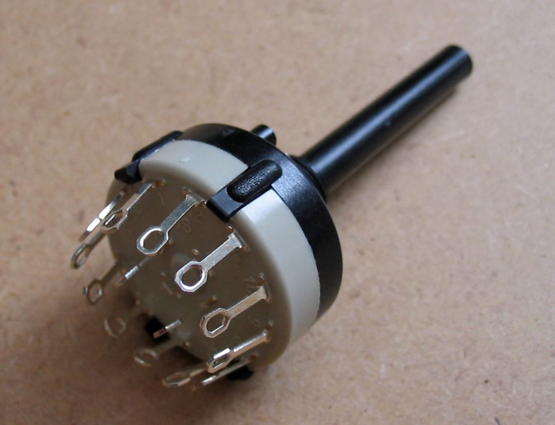
you can actually adjust the number of positions in case you want less than 12. With 4 switches you have the most
options but also a couple that will produce the same result. So there might be a way to use 2 double pole 6 position
switches (2x6), switching 2 capacitors at once that will give you the same options without having duplicate settings.
| Quote: | | 2. what capacitor position on the board do i connect the switch to? (there are 5 unique cap positions on the board) |
I expect that 4 capacitors are used for the frequency of the oscillators and the 5th one is either a decoupling cap
for the power or it's used at the output. The ones for the oscllators all have the - sides connected together so you
only have to switch the + side.
| Quote: | | 3. any suggestions on a range of capacitor values? |
you're probably good with capacitors in the range of 1nF to 100uF. With these oscillators doubling the capacity
will result in half the frequency. But this also goes for the resistor value with you set with the pots. So 1nF, 10nF,
100nF etc will most likely work fine.
| Quote: | | 4. do i need to mess with resistor values when i do this? |
no need for that and I would keep the 100K pots.
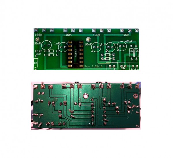
If you can take some clear photos of both sides of the PCB I can figure out how it works and determine
what would be most useful to use for the switches and capacitors.
_________________
"My perf, it's full of holes!"
http://phobos.000space.com/
SoundCloud BandCamp MixCloud Stickney Synthyards Captain Collider Twitch YouTube |
|
|
Back to top
|
|
|
spectreman
Joined: Mar 24, 2015
Posts: 12
Location: Milwaukee
|
| Posted: Thu Apr 02, 2015 8:52 am Post subject:
|
|
|
Thanks for the reply!
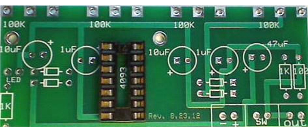
so, i attached the front and back of the board (please excuse the beginner solder job).
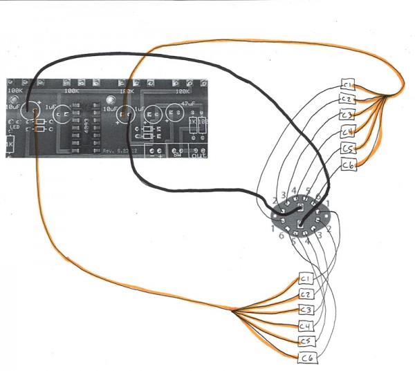
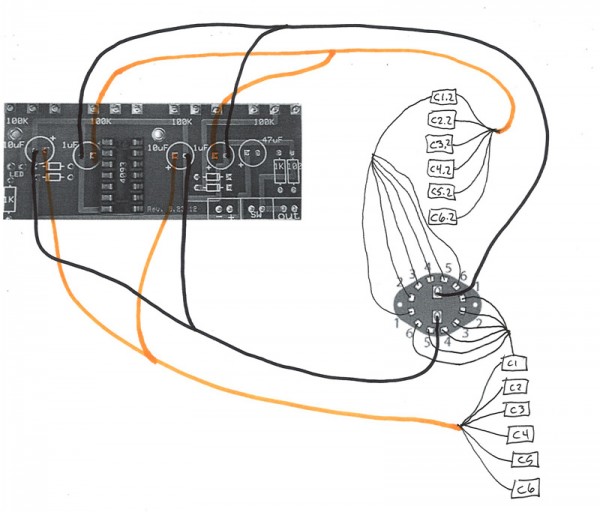
i'm going to go with a 2 pole 6 position switch for now, i also attached a drawing of how my brain is understanding the circuit...am i thinking about this correctly?
please let me know what suggestions you have as far as range of capacitors go. i'll keep switch position (1) as the initial 1uf and 10uf that is noted on the board, and raise cap values for switch position 2 through 6.
really, thanks for your help. it's a bit intimidating, but a lot of fun.
| Description: |
|
| Filesize: |
170.93 KB |
| Viewed: |
346 Time(s) |
| This image has been reduced to fit the page. Click on it to enlarge. |
|
| Description: |
|
| Filesize: |
114.04 KB |
| Viewed: |
243 Time(s) |
| This image has been reduced to fit the page. Click on it to enlarge. |
|
|
|
|
Back to top
|
|
|
spectreman
Joined: Mar 24, 2015
Posts: 12
Location: Milwaukee
|
|
|
Back to top
|
|
|
PHOBoS
Joined: Jan 14, 2010
Posts: 5881
Location: Moon Base
Audio files: 709
|
| Posted: Thu Apr 02, 2015 4:44 pm Post subject:
|
|
|
| spectreman wrote: | wait...i'm making this too complicated i think.
on the board, the 10uf caps modulate the 1uf, right? so i just need the switch i'm adding to go to the (2) spots labeled 10uf.
i think this new drawing is correct... |
you almost got it, you just need to flip the wires going to the PCB. (it's an improvement over the previous one though)
So from the PCB you take the + side of where the capacitor was to the switch contact and wire all the + sides of the capacitors you're
adding to the switch. and all the - sides of the capacitors are connected together and to the - side of where the capacitor was on the PCB.
however it's not the 10uF's modulating the 1uf's which is why I needed the photos. I had 2 ideas of how it would most likely be connected:
1: 4 seperate oscillators just mixed together with the diodes.
2: two groups of 2 oscillators with the low frequency ones (10uF) modulating the higher frequency ones (1uF)
And as it turns out it's number 1. They still cause a modulation effect though.
So you might want 2 of those switches which makes it possible to change all the capacitors. but that's up to you.
I'll do some tests myself to see what are the most useful combinations.
_________________
"My perf, it's full of holes!"
http://phobos.000space.com/
SoundCloud BandCamp MixCloud Stickney Synthyards Captain Collider Twitch YouTube |
|
|
Back to top
|
|
|
spectreman
Joined: Mar 24, 2015
Posts: 12
Location: Milwaukee
|
|
|
Back to top
|
|
|
PHOBoS
Joined: Jan 14, 2010
Posts: 5881
Location: Moon Base
Audio files: 709
|
| Posted: Fri Apr 03, 2015 9:06 am Post subject:
|
|
|
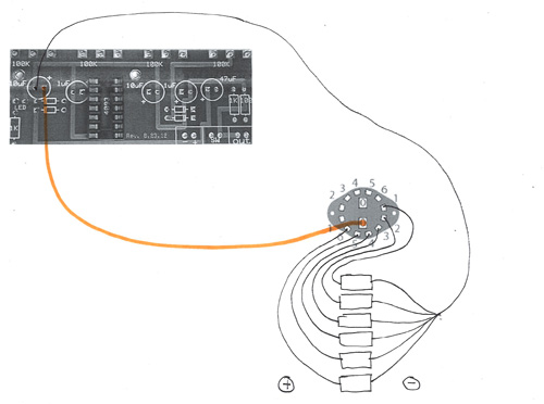
yes that's it 
It's not that your previous version wouldn't have worked, but it's more common to connect all the - sides together
and because all the capacitors on the board have them connected too you will only need 1 wire for all of them if you do
it this way. (so that's 5 wires in total). I hope to do a test later today or else this weekend and I'll let you know my findings.
_________________
"My perf, it's full of holes!"
http://phobos.000space.com/
SoundCloud BandCamp MixCloud Stickney Synthyards Captain Collider Twitch YouTube |
|
|
Back to top
|
|
|
PHOBoS
Joined: Jan 14, 2010
Posts: 5881
Location: Moon Base
Audio files: 709
|
|
|
Back to top
|
|
|
spectreman
Joined: Mar 24, 2015
Posts: 12
Location: Milwaukee
|
| Posted: Sat Apr 04, 2015 1:50 pm Post subject:
|
|
|
oh man...you rule!
perfect.
i have to order some parts, but i'll post a photo when it's done. thanks a million for all the help...i appreciate your instruction and help more than you can imagine. |
|
|
Back to top
|
|
|
PHOBoS
Joined: Jan 14, 2010
Posts: 5881
Location: Moon Base
Audio files: 709
|
|
|
Back to top
|
|
|
spectreman
Joined: Mar 24, 2015
Posts: 12
Location: Milwaukee
|
| Posted: Mon Apr 06, 2015 2:41 pm Post subject:
|
|
|
| PHOBoS wrote: | | those diodes are actually zener diodes, which makes some difference in sound.[/i] |
with the getlofi kit, 4.7 Volt .5 Watt zener diodes were supplied...can i use say,
4.7 Volt 1 Watt, or other value?
how does a different value zener diode affect sound? |
|
|
Back to top
|
|
|
PHOBoS
Joined: Jan 14, 2010
Posts: 5881
Location: Moon Base
Audio files: 709
|
| Posted: Tue Apr 07, 2015 10:49 am Post subject:
|
|
|
Honestly I can't tell without testing it. I only once used a zenerdiode in a circuit like this and that was actually by accident. A happy accident though 
In this circuit I think they might produce somewhat of a stepped voltage.
If I just look at 2 oscillators then when both are high the output will be roughly 9V (a bit less because of the voltage drop across the diodes).
when 1 is high and 1 is low the voltage should be around 4.7V and when both are low the diodes are blocking it, but because the ouput is
connected to GND through a resistor it's probably 0V. So instead of having an output that is either 0 or 9V you'll get an extra voltage halfway
in between. So if you use zenerdiodes with a different voltage for each oscillator you might get more variation.
This only what I think is happening, I could be wrong.
1Watt zeners will probably work but a zenerdiode needs a certain current flowing throw it to properly work so I can't really tell how much
that would affect it.
_________________
"My perf, it's full of holes!"
http://phobos.000space.com/
SoundCloud BandCamp MixCloud Stickney Synthyards Captain Collider Twitch YouTube |
|
|
Back to top
|
|
|
spectreman
Joined: Mar 24, 2015
Posts: 12
Location: Milwaukee
|
| Posted: Thu Apr 30, 2015 7:40 am Post subject:
|
|
|
hey there again...
on you schematic, where you say "to + side of 10uf capacitor", you mean to the + side of where it is labeled on the getlofi board, correct?
i'm not actually going from the switch to a capacitor on the board, just to where a capacitor used to be on the board, right? |
|
|
Back to top
|
|
|
PHOBoS
Joined: Jan 14, 2010
Posts: 5881
Location: Moon Base
Audio files: 709
|
|
|
Back to top
|
|
|
|

 Forum index » DIY Hardware and Software