| Author |
Message |
croatan

Joined: Apr 20, 2015
Posts: 8
Location: Switzerland
|
 Posted: Thu Apr 30, 2015 5:59 am Post subject: Posted: Thu Apr 30, 2015 5:59 am Post subject:
 Let's get going: Lunetta Modular Let's get going: Lunetta Modular
Subject description: Kick off advice & progress blog |
  |
|
Hi folks!
First off: A huge thanks to you all for the advice that can be found on here - without this forum, my journey into the world of DIY noise makers wouldn't have been as easy, as it has been now.. You're all awesome!
After some circuit bending and building some 555/40106 oscillators and a 386 amplifier I got hooked on making my own noise machines. Soldering > socializing, as I've read on here - luckily my partner is overseas for another two months and as I'm working at a concert venue, I've got the excuse of "training my electronic skills for audio engineering" 
Now, as the next step after building an APC with a 4017 five step sequencer, I'd like to tackle an old dream of building a modular system. The last ICs are on their way and before I start, I'd like to confirm some basics to protect my ICs (I've fried a couple 555s and two 40106s..). I've got no deeper knowledge in electronics, so please help me confirm some "thumb rules", which I found all over the forums - with some different values though:
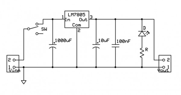
Decoupling. I'll decouple every IC with a 100nf capacitor from V+ to GND. I'll decouple every PCB (with one or multiple chips) with V+ -> 100uf -> 100nf -> GND. And I'll put a LM7805 regulator after the wall wart (probably 9V). Are those good thumb values?
Routing. I'll try to route all grounds on a board to a single GND connection coming from the main power supply. How important is that? As that might become quite frustrating..
Inputs/Outputs. I'll pull all unused inputs low with 100k -> GND. If standard high: 100k -> V+. I'll put in a 4001 diode as well, to have stackable inputs.
All patchable outputs will go through a 1k resistor and a 4001 diode (for stackability). Are the diodes necessary? Will they modify the sound in any way that I'd need additional parts?
Connections. I got a shitload of cinch sockets for cheap and even more cinch cables lying around. I haven't seen a lunetta system using cinch connectors - but that shall be no problem, right? I'll just leave the ground unconnected on the plugs and use the pin.
Thanks a lot for your help!
I'll use this thread as a progress blog. Though it may take two to three weeks till I'll be able to post the first builds (shipping from china...)
I'm looking forward to running my lunetta system through our club PA (that's why I love working as an audio engineer  ), if they "behave" through my guitar amplifier. Probably a good way to kick people out at the end of the night as well. Last weekend I confused some stoned folks with my APC running over our lovely (and loud) speakers when we we're closing down.. Dig that. ), if they "behave" through my guitar amplifier. Probably a good way to kick people out at the end of the night as well. Last weekend I confused some stoned folks with my APC running over our lovely (and loud) speakers when we we're closing down.. Dig that.
Love,
croatan |
|
|
Back to top
|
|
 |
PHOBoS

Joined: Jan 14, 2010
Posts: 5873
Location: Moon Base
Audio files: 709
|
Posted: Thu Apr 30, 2015 6:47 am Post subject:
Re: Let's get going: Lunetta Modular
Subject description: Kick off advice & progress blog |
|
|
 
| Quote: | | Decoupling. I'll decouple every IC with a 100nf capacitor from V+ to GND. I'll decouple every PCB (with one or multiple chips) with V+ -> 100uf -> 100nf -> GND. And I'll put a LM7805 regulator after the wall wart (probably 9V). Are those good thumb values? |
Sounds good. I didn't put a regulator in it myself, I just hook up to a regulated supply. This has the advantage that
I can run it at different voltages which is useful when using it to control something else. 5V outputs often won't trigger
something running on 12V, but 12V would be too high if I want to control something that runs on 5V.
| Quote: | | Routing. I'll try to route all grounds on a board to a single GND connection coming from the main power supply. How important is that? As that might become quite frustrating. |
Having a seperate GND/power connection for each circuit is better than chaining them from one to the other.
But for digital circuits it matters a bit less except for the oscillators.
| Quote: | Inputs/Outputs. I'll pull all unused inputs low with 100k -> GND. If standard high: 100k -> V+. I'll put in a 4001 diode as well, to have stackable inputs.
All patchable outputs will go through a 1k resistor and a 4001 diode (for stackability). Are the diodes necessary? Will they modify the sound in any way that I'd need additional parts? |
- I noticed that for some chips a smaller resistor works better, most of the time 100K will do fine but in case something
doesn't work correct you could try if making it smaller helps. I usually add an inverter using a transistor to standard high pins.
- 1K resistors will protect the outputs in case of shorts, the diodes make it possible to connect more of them
to one input (stackable). This will create an OR gate together with the 100K pulldown on the inputs. It will
not work if you have a pullup resistor on the input, hence why I use the inverters. If you leave the diodes
out you could still connect more than one output to a single input but it would result in a varying voltage
and digital chips get confused by those. 
- There's no need for diodes on the inputs unless you add multiple inputs or might connect it to something
that has a negative output. btw You can use 4148 or similar diodes, 4001 works fine but is usually slightly
more expensive.
| Quote: | | Connections. I got a shitload of cinch sockets for cheap and even more cinch cables lying around. I haven't seen a lunetta system using cinch connectors - but that shall be no problem, right? I'll just leave the ground unconnected on the plugs and use the pin. |
I see no problems using cinch connectors and you could use the GND connection too.
Have fun! 
_________________
"My perf, it's full of holes!"
http://phobos.000space.com/
SoundCloud BandCamp MixCloud Stickney Synthyards Captain Collider Twitch YouTube |
|
|
Back to top
|
|
|
Steveg

Joined: Apr 23, 2015
Posts: 184
Location: Perth, Australia
|
| Posted: Thu Apr 30, 2015 7:43 am Post subject:
|
|
|
Hello Crotan, I'm also about to start building my first Lunetta but I do have some decades experience with logic chips.
| Quote: | | And I'll put a LM7805 regulator after the wall wart (probably 9V). Are those good thumb values? |
Minimum voltage for CMOS chips is 3 volts so regulating the input to 5 volts is cutting things a bit fine unless you know what you are doing. If you have a modern regulated DC wall wart then further regulation is not needed. I chose a 12 volt 2 amp because I thought I might want to build in a small amplifier kit. There seem to be plenty of posts here about 9 volt Lunettas.
| Quote: | | All patchable outputs will go through a 1k resistor and a 4001 diode (for stackability). Are the diodes necessary? Will they modify the sound in any way that I'd need additional parts? |
I would stay away from the diodes unless the circuit you are copying has them. There will be times when you will want to use the current sinking capability of the CMOS chip and the diode will prevent that. I was going to add current limiting resistors on the outputs but then I saw that no-one else did so I'll only be adding them if I think there is a possibility of heavy current draw.
Watch out for the current draw of LEDs. Make sure the chip can handle the LED current as well as whatever musical thing you want it to do. |
|
|
Back to top
|
|
|
SUGARAT
Joined: Jan 21, 2015
Posts: 19
Location: California
Audio files: 1
|
| Posted: Thu Apr 30, 2015 12:52 pm Post subject:
|
|
|
When building my modular, I started to run into troubles after about 15 chips or so. Building my own regulated 9v power supply, cleaning up the power bus, and adding a couple large decoupling caps where the power splits to all the circuits made the problems go away and now I am still adding more modules and everything is working fine!
So yeah I say being mindful of the routing to ground is important. It may save you lots of time down the line and will also be more organized and easier to work with as your synth slowly transforms into several cubic feet of solid spaghetti.
Good luck. You are going have so much fun! |
|
|
Back to top
|
|
|
elektrouwe
Joined: May 27, 2012
Posts: 146
Location: Germany
|
Posted: Thu Apr 30, 2015 2:10 pm Post subject:
Re: Let's get going: Lunetta Modular
Subject description: Kick off advice & progress blog |
|
|
power supply voltage: my modular Lunetta uses <7V> 6.9V) why?:
- 74HC chips and CD4000 can be mixed (9V would be too high)
- CD4000 series to directly drive LEDs with 1mA without compromising output levels (5V would be too low)
- Analog switches 4066,405x have useful Ron ; 74HC4066/74HC405x even better (5V would be too low)
- output current limiting resistor is not needed (needed for >=9V)
I would not use chinch connectors : they a good for "connect once and forget" but not for "dynamic patching"
banana plugs rule 
Input protection is important if you don't play barefoot or use other anti-ESD measures. I use 47k on all jack inputs.
resistors on unused or internal inputs do not improve anything.
PS: tomorrow (Fr.1.5.) we have a Lunetta Developers Gathering near Tübingen,D; maybe a 2h ride for you from CH ?
please check you PM |
|
|
Back to top
|
|
|
PHOBoS
Joined: Jan 14, 2010
Posts: 5873
Location: Moon Base
Audio files: 709
|
Posted: Thu Apr 30, 2015 2:49 pm Post subject:
Re: Let's get going: Lunetta Modular
Subject description: Kick off advice & progress blog |
|
|
| elektrouwe wrote: | I would not use chinch connectors : they a good for "connect once and forget" but not for "dynamic patching"
banana plugs rule |
True, cinch connectors would work, but maybe not be reliable for very long. Bananas would be my #1 choice too, but they're a bit
out of my price range (especially the nice cables) so i use the bolts and crocks method instead.
_________________
"My perf, it's full of holes!"
http://phobos.000space.com/
SoundCloud BandCamp MixCloud Stickney Synthyards Captain Collider Twitch YouTube |
|
|
Back to top
|
|
|
commathe

Joined: Jul 26, 2013
Posts: 153
Location: Beijing
Audio files: 5
|
| Posted: Sun May 03, 2015 9:54 pm Post subject:
|
|
|
I have a site dedicated to this, though it is going to be a little while before it gets updated as I prepare to move countries
http://castlerocktronics.com/modular.html |
|
|
Back to top
|
|
|
croatan
Joined: Apr 20, 2015
Posts: 8
Location: Switzerland
|
| Posted: Tue May 05, 2015 3:35 pm Post subject:
|
|
|
Thank you all for the advice! What a warm welcome
Regarding the inputs I got a good idea of what's necessary and what not.. I'll try around with some different resistors for protection (47k-100k).
Regarding the output diodes: @Steveg: I actually got the idea from commathes page (linked in the post before). But somehow I've overread the part about current sinking. I'll look into details, when I want to use diodes on the outputs and when not. But as it seems it can't be taken as a general, useful safety rule.
Regarding power supply: I'll think some more about the chips I'd like to use and decide on a supply voltage. elektrouwe's suggestion with 7V does sound quite versatile though. And I'll for sure take my time for a good GND routing.
I'll probably look around for a good deal on banana plugs. I just got myself a shitload of work for the next weeks and some parts are still on their way, so I got to wait anyway.. But that probably means I can afford bananas
@commathe: I'm well aware of your page and got it bookmarked for the start of my lunetta. Beautifully prepared information and very welcoming for a beginner!
I'll keep you updated! Next post should be pics of a first module in a few weeks  Till then I'll be drooling over the build threads and the schematics here. Till then I'll be drooling over the build threads and the schematics here.
Love,
croatan
EDIT: And I may stick with a semi-modular lunetta-in-a-box for this first lunetta build. Somehow that makes me feel a little bit more comfortable: Breadbording, preparing a box with all the controls and sockets mounted, and then "just" soldering action. Otherwise I'd probably get distracted a little bit more or suddenly I'd have to change stuff in the older modules because I want to add some crazy shit  |
|
|
Back to top
|
|
|
croatan
Joined: Apr 20, 2015
Posts: 8
Location: Switzerland
|
|
|
Back to top
|
|
|
rico C
Joined: Feb 27, 2014
Posts: 26
Location: Redondo Beach
|
| Posted: Wed Jul 08, 2015 9:02 am Post subject:
|
|
|
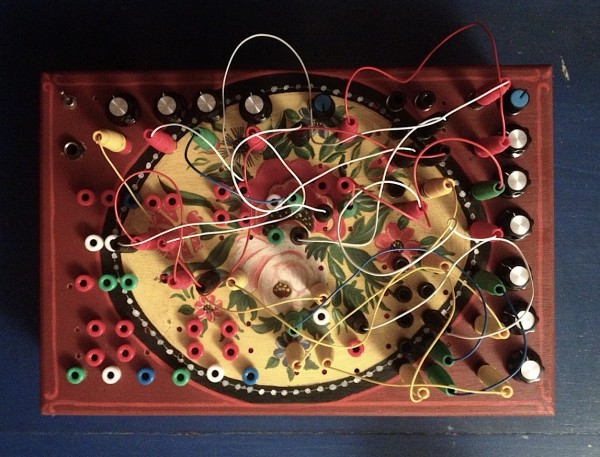
I just wanted to say that is a very cool looking box, nicely done!
Surely you need to clock the counter and divider before they can clock anything else...apologies if I'm not understanding the problem. |
|
|
Back to top
|
|
|
PHOBoS
Joined: Jan 14, 2010
Posts: 5873
Location: Moon Base
Audio files: 709
|
| Posted: Wed Jul 08, 2015 9:44 am Post subject:
Re: Help :-( |
|
|
It's a hard to tell what's wrong without a schematic so here' s some info that might be helpful:
4017: pin 13 needs to be connected to GND. Pin 15 (reset) needs to be low, I assume you're
using a pullup pulldown resistor for this but you could try connecting it directly to GND to see if that makes
any difference. Same with the 4040: try connecting the reset directly to GND.
nice looking box 
_________________
"My perf, it's full of holes!"
http://phobos.000space.com/
SoundCloud BandCamp MixCloud Stickney Synthyards Captain Collider Twitch YouTube
Last edited by PHOBoS on Wed Jul 08, 2015 10:37 am; edited 1 time in total |
|
|
Back to top
|
|
|
croatan
Joined: Apr 20, 2015
Posts: 8
Location: Switzerland
|
| Posted: Wed Jul 08, 2015 10:08 am Post subject:
|
|
|
Hey folks,
Thanks for your fast answers!
@Phobos: I tried connecting them directly to the ground - no difference though.
Maybe I didn't state the problem clearly, sorry...
40106 -> 4017 // everything nice, 4017 blinking, can hear the outputs
40106 -> 4040 // everything nice'n'blinky, can listen to outputs
40106 -> 4017 -> 4040 // doesn't get any 4017 output recognized as clock for 4040.
40106 -> 4040 -> 4017 (clock) // doesn't recognize any 4040 output as clock for 4017.
40106 -> 4040 -> 4017 (reset) && 40106 -> 4017 (clock) // works as expected, the output from 4040 does reset the 4017, clock speed changes are fine as well
I'll draw a schematic later on though, saturday should work... but it's basically just every output to the patchbay through 1k res. Inputs to patchbay through 100k res. 100nf as decoupler. resets grounded (either way, directly or through res. doesn't make a difference)..
I thought the problem may be incompatibility or too much resistance... but without the resistors nothing changes 
I'm really excited about this lil' noise maker.. Thanks for your help folks!
(Got the box out of a thrift store... gotta love thrift stores <3 ) |
|
|
Back to top
|
|
|
SUGARAT
Joined: Jan 21, 2015
Posts: 19
Location: California
Audio files: 1
|
| Posted: Wed Jul 08, 2015 5:06 pm Post subject:
|
|
|
| you are using decoupling capacitors, yeah? what size? |
|
|
Back to top
|
|
|
Steveg
Joined: Apr 23, 2015
Posts: 184
Location: Perth, Australia
|
| Posted: Thu Jul 09, 2015 2:25 am Post subject:
|
|
|
| croatan wrote: |
40106 -> 4017 // everything nice, 4017 blinking, can hear the outputs
40106 -> 4040 // everything nice'n'blinky, can listen to outputs
|
As PHOBoS said it is difficult to tell without the schematic but my best guess is that the LED's are loading down the gate outputs too much.
Try a multimeter on the chip outputs ... If it reads less than 0.25 times your supply voltage you aren't getting enough voltage to trigger a high logic level.
Otherwise (or to be sure) just disconnect one LED and see if that output will now drive another chip.
Those LEDs need to be drawing less than one milliamp use high output LEDs and size your resistor to that current. |
|
|
Back to top
|
|
|
croatan
Joined: Apr 20, 2015
Posts: 8
Location: Switzerland
|
| Posted: Thu Jul 09, 2015 5:29 am Post subject:
|
|
|
| Steveg wrote: | | croatan wrote: |
40106 -> 4017 // everything nice, 4017 blinking, can hear the outputs
40106 -> 4040 // everything nice'n'blinky, can listen to outputs
|
As PHOBoS said it is difficult to tell without the schematic but my best guess is that the LED's are loading down the gate outputs too much.
Try a multimeter on the chip outputs ... If it reads less than 0.25 times your supply voltage you aren't getting enough voltage to trigger a high logic level.
Otherwise (or to be sure) just disconnect one LED and see if that output will now drive another chip.
Those LEDs need to be drawing less than one milliamp use high output LEDs and size your resistor to that current. |
MAY YOU LIVE LONG AND PROSPER
(...while stupid me is off replacing resistors  ) )
Thank you all folks! I'll be able to stay away from drawing schematics a little bit longer...
EDIT: OMFG IT'S ALIVE |
|
|
Back to top
|
|
|
PHOBoS
Joined: Jan 14, 2010
Posts: 5873
Location: Moon Base
Audio files: 709
|
|
|
Back to top
|
|
|
Steveg
Joined: Apr 23, 2015
Posts: 184
Location: Perth, Australia
|
| Posted: Fri Jul 10, 2015 1:41 am Post subject:
|
|
|
Oh Good!
Nice box BTW! |
|
|
Back to top
|
|
|
blue hell
Site Admin

Joined: Apr 03, 2004
Posts: 24493
Location: The Netherlands, Enschede
Audio files: 298
G2 patch files: 320
|
| Posted: Fri Jul 10, 2015 2:00 am Post subject:
|
|
|
Very nice box even :-)
_________________
Jan
also .. could someone please turn down the thermostat a bit.
 |
|
|
Back to top
|
|
|
elektrouwe
Joined: May 27, 2012
Posts: 146
Location: Germany
|
| Posted: Fri Jul 10, 2015 2:27 am Post subject:
|
|
|
| Blue Hell wrote: | | Very nice box even |
don't drink and drill ! |
|
|
Back to top
|
|
|
croatan
Joined: Apr 20, 2015
Posts: 8
Location: Switzerland
|
| Posted: Fri Jul 10, 2015 2:34 pm Post subject:
|
|
|
| PHOBoS wrote: | ah the LED's good thinking steve, they can indeed cause a voltage drop.
Makes me curious though, what was the value of the resistors ? |
erhm.. 220r. during sorting my parts (and before I got a multimeter) i put them in the same bag as my 2k2 ...  But I learned something, didn't I But I learned something, didn't I
@Blue Hell, Steveg: Cheers mates =) I'm really happy about it too!
@elektrouwe: I did measure the distances... but well.. I usually find time to work on the synth late at night... after work... which often is followed by free beer. But it has to look handmade, doesn't it 
I'm gonna put some sound samples up soon, but at the moment my interface isn't setup and I rather spend time soldering, than putting my recording gear up at home. They'll come soon, I'm making good progress. Just finished the 4015 shift registers.. Can't decide on whether to make a 4046 VCO or the gates first.
Love,
croatan
EDIT: What a great community this is!
EDIT2: Fuck it. It's 3am over here, got to work tomorrow, tired as hell, but I built the melody generator, and my baby is making some noise (video link) : 40106 Oscillators, 4015 Shift Registers, 4040 divider, slacker melody gen. Loving it. Sorry for bad filming, need some sleep. |
|
|
Back to top
|
|
|
croatan
Joined: Apr 20, 2015
Posts: 8
Location: Switzerland
|
|
|
Back to top
|
|
|
Steveg
Joined: Apr 23, 2015
Posts: 184
Location: Perth, Australia
|
| Posted: Tue Jul 14, 2015 3:52 am Post subject:
|
|
|
I see no reason why you can't replace the battery with a plug pack. One Amp will be more than enough.
The only caveat is make sure of the polarity. In fact it would not hurt to put a power diode between the power plug and the regulator. |
|
|
Back to top
|
|
|
rico C
Joined: Feb 27, 2014
Posts: 26
Location: Redondo Beach
|
| Posted: Wed Jul 15, 2015 8:18 am Post subject:
|
|
|
| sounds fabulous! glad you got it working. |
|
|
Back to top
|
|
|
|

 Forum index » DIY Hardware and Software » Lunettas - circuits inspired by Stanley Lunetta


 It's just incredible how much information can be found on here..