| Author |
Message |
synaesthesia

Joined: May 27, 2014
Posts: 291
Location: Germany
Audio files: 85
|
 Posted: Sat Nov 28, 2015 11:06 am Post subject:
Patch 22 Posted: Sat Nov 28, 2015 11:06 am Post subject:
Patch 22
Subject description: Do you have a few 22K resistors left? |
  |
|
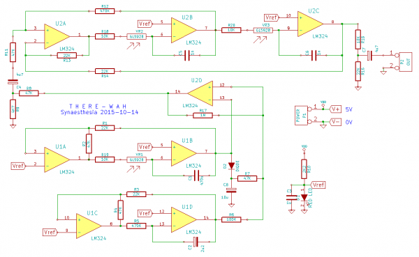
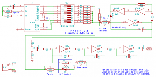
Playing around with filters lately, I had a great sounding Op-Amp filter on my breadboard and wondered if the same could be built with CMOS inverters. Indeed, there are some circuits on the web already. So I built one of these using three 4049 inverters and it works just great. Of course, there needs to be some musical input, so I put together a simple pattern generator from a 4060 counter as well. The outputs of the 4060 counter are mixed via 22K resistors and produce a voltage sequence that drives a VCO built from the other three 4049 inverters. This produces several (2^6=64) different melodies, depending on the counter frequencies selected via the DIP switch. The two 4060 counter outputs with the highest frequencies are reserved to modulate the filter via a DIY vactrol.
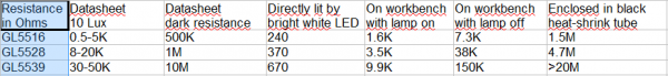
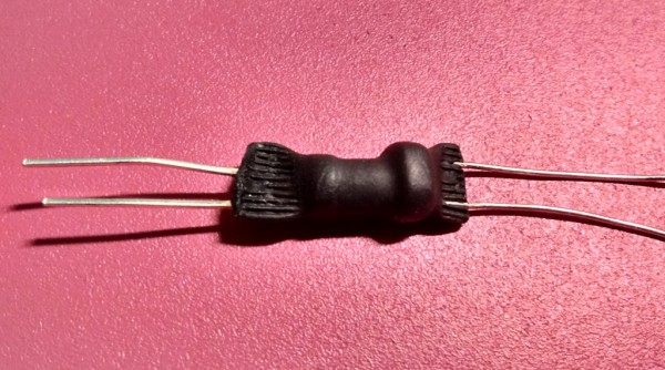
I built several vactrols with the LEDs and LDRs I had at hand. The best working ones do not use super bright LEDs, but normal diffused red ones. Rather old LEDs, that are not as bright as modern ones, tend to work better. The LDR is a cheap standard type like the GL5516 or GL5528, that you can get in quantities at ebay. It is very important to seal them together in a light-tight package. I used a 15mm long piece of heat-shrink tube for the package. Because your mileage may vary considerably with these DIY vactrols, I put two pots into the circuit (RV2 and RV3) that can be used to compensate the variations. Nevertheless, you might need to experiment a bit here.
Looking at the almost complete schematic, I noticed that most of the resistors used were 22K. Even the capacitors had the 2.2 signature. So just for the fun of it I aimed at making all of them 22K. I could hardly resist to use two 22K resistors in series instead of R18 with 47K, but that would have violated my minimum-parts doctrine.  The name of the circuit was obvious then: Patch 22. The name of the circuit was obvious then: Patch 22.
In the recording I start with a slow tempo and fixed melody. Then I change the resonance of the filter from minimum to maximum and back to a middle setting. After increasing the tempo, I changed the DIP switch settings at A2 to A8 for the melody. Because of the slow tempo most of them are not complete, and so sound rather similar. At the end I changed the filter settings at A0 and A1, and finally turned the filter modulation off completely for the last few seconds.
Lots of fun and room for experimentation with just two CMOS chips.
| Description: |
|
| Filesize: |
329.71 KB |
| Viewed: |
500 Time(s) |
| This image has been reduced to fit the page. Click on it to enlarge. |
|
| Description: |
|
| Filesize: |
64.76 KB |
| Viewed: |
667 Time(s) |
| This image has been reduced to fit the page. Click on it to enlarge. |
|
| Description: |
|

Download (listen) |
| Filename: |
Patch 22.mp3 |
| Filesize: |
2.17 MB |
| Downloaded: |
995 Time(s) |
|
|
|
Back to top
|
|
 |
piedwagtail

Joined: Apr 15, 2006
Posts: 297
Location: shoreditch
Audio files: 3
|
| Posted: Sun Nov 29, 2015 10:51 am Post subject:
|
|
|
Super!
I bought and played with a lot of those LDRs.
I'm not sure what you found to be the best resistance range vs brightness.
fyi
My findings with a modern yellow led were lowest resistance for
GL5516 300
GL5528 600
GL5537 600
GL5549 2k
and highest resistance being
GL5516 37k
GL5528 680k
GL5537 1M5
GL5549 27M
GL5528 and GL5537 were similiar to 1k then changed linearity with further decrease in current
Ebay codes were
SKU125809
SKU125807
SKU125806
SKU090608
R |
|
|
Back to top
|
|
|
richardc64

Joined: Jun 01, 2006
Posts: 679
Location: NYC
Audio files: 26
|
|
|
Back to top
|
|
|
synaesthesia
Joined: May 27, 2014
Posts: 291
Location: Germany
Audio files: 85
|
|
|
Back to top
|
|
|
synaesthesia
Joined: May 27, 2014
Posts: 291
Location: Germany
Audio files: 85
|
|
|
Back to top
|
|
|
synaesthesia
Joined: May 27, 2014
Posts: 291
Location: Germany
Audio files: 85
|
| Posted: Wed Dec 02, 2015 12:24 pm Post subject:
|
|
|
| richardc64 wrote: | | I used a 4069, but it might work with 4049. |
Just had it on the breadboard and can confirm that it does work with a 4049 as well. I also tried a 4069UBE and a 4069UBP and both work. The filter does not work with a 40106, although you get some signal out of it.
However, there is very little control over the resonance and to me the sound is no match to the one using three inverters. That one actually should work with a 4069 as well. |
|
|
Back to top
|
|
|
|

 Forum index » DIY Hardware and Software » Lunettas - circuits inspired by Stanley Lunetta