| Author |
Message |
Cfish

Joined: Feb 24, 2016
Posts: 477
Location: Indiana
|
|
|
Back to top
|
|
 |
Cfish
Joined: Feb 24, 2016
Posts: 477
Location: Indiana
|
|
|
Back to top
|
|
|
etheory
Joined: Feb 20, 2013
Posts: 13
Location: Sydney
|
 Posted: Mon May 02, 2016 8:22 pm Post subject:
Re: A few VCA questions Posted: Mon May 02, 2016 8:22 pm Post subject:
Re: A few VCA questions |
  |
|
Having dealt quite a lot with circuits of this description, I'll attempt to help.
| Cfish wrote: | I have a few questions I'm hoping you folks of far greater experience and knowledge can give me a little guidance on.
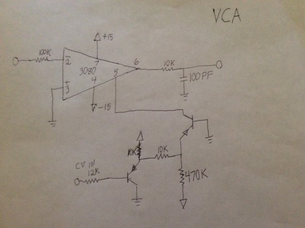
It will be between a triangle VCO and a basic low pass VCF? |
I don't think the circuit, as presented, will work as you intend it to.
If it's meant to be a VCA, then connect the output 10K and 100pF in parallel from the OTA output to ground. The 10K will set the output voltage as a function of the bias current and Gm, and the 100pF will act as a low pass filter.
If it's meant to be a VCF, then connect the 100pF directly to ground without the 10K resistor, then buffer the output, the tie the buffered output back to the -ve input via a 100K resistor. That will make a unity-gain low pass VCF whose centre frequency is controlled via the pin 5 bias current.
| Cfish wrote: | | What risks do I run not having a buffer on the output? |
The CA3080 is an Operational Transconductance Amplifier, and hence it has a current output.
A current output expects, in general, one of two things:
1.) To be shorted directly to a virtual ground.
2.) To be connected to a resistor-to-ground, then connected to a high impedance buffer.
Many other configurations are possible, and sometimes used in older circuit designs, but one of the two above will give you the best theoretical result with respect to noise and output swing.
Remember that since the 3080 is a current output, as the resistive load increases (the resistor value decreases), due to V=IR, the output voltage will decrease as R decreases (the load increases) for a constant I (constant I is ensured with a current output).
Output swing is limited to 1.2V within +V and -V. This is due to the wilson current mirrors it uses at the output. Each of these current mirrors drop 2 diode drops (0.6V * 2) to operate. Hence the circuit needs 1.2V from each rail to work properly. Outside this limit it will hard clip.
Input swing is about 20-30mV due to the input being directly into a transistor long tailed pair. This input arrangement has an approximately arc-tangent input distortion curve, that has a tiny linear range within about +-15mV (hence 3080 circuits often heavily attenuating their inputs to avoid distortion).
So the buffer serves to provide a very high impedance load, so that the output of the 3080 doesn't change gain with dynamic load (i.e. it separates your intended R load from the load it is driving).
This is important for constant gain at the output.
| Cfish wrote: | | Do any values look out of whack for +- 15 v ? |
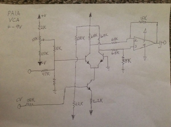
Not from a ballpark point of view, no, but clearly if your circuit was originally designed for +-9V, at 15V, with the same parts, you'll be pushing a higher current through it, which may, or may not, decrease performance.
| Cfish wrote: | | Was trying to understand any current and voltage limitations that need to be honored with respect to pin 5 |
Pin 5 is a current-mirror input. It's actually supposed to be a current-mode-input, so it sits nominally at -V, and as you increase the input current, the current through the mirror increases, and hence the bias current to the OTA core increases, increasing the gain.
The way it's configured in your schematic, the input PNP is merely a voltage buffer (that additionally raises the input voltage by 0.6V which avoids the "dead-zone" of the following PNP transistor that requires approx 0.6V to be "on"), and the second PNP is a voltage to current converter (along with the 10K/470K divider). In this configuration the voltage at the PNP emitter is "reflected" around the grounded base to the collector, and that current is presented to the current mirror at pin 5. If the PNP emitter is at ground potential, then the transistor is "off" and no current flows. As the emitter is moved above ground (specifically around 0.6V above ground), current can flow, and the current to pin 5 increases.
As a general rule, don't feed more than 500uA to pin 5, or you'll risk frying the chip at worst, or creating huge amounts of distortion as the input transistors saturate.
Hope that helps. |
|
|
Back to top
|
|
|
LFLab
Joined: Dec 17, 2009
Posts: 497
Location: Rosmalen, Netherlands
|
|
|
Back to top
|
|
|
Cfish
Joined: Feb 24, 2016
Posts: 477
Location: Indiana
|
| Posted: Tue May 03, 2016 5:12 pm Post subject:
|
|
|
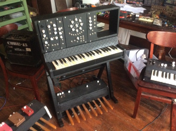
Thanks Ethory. That helped a lot. Looks like if I swing the resistor to ground as you pointed out after the OTA I am pretty much ok in my application. I had placed the filter there because my keyboard circuit idles the VCO two notes above the top key, and it was bleeding through. The low pass VCF it will be hard wired in to has an input buffer, and will eliminate my need for the passive filter.
My 79L09s came today. So I can try the PAIA circuit on the correct voltage.
Thanks LFLab. Awesome link. Great information there, and some fun schematics to experiment with. |
|
|
Back to top
|
|
|
etheory
Joined: Feb 20, 2013
Posts: 13
Location: Sydney
|
| Posted: Wed May 04, 2016 2:24 am Post subject:
|
|
|
| Cfish wrote: | | Thanks Etheory. That helped a lot. |
You are welcome, good to hear.
| Cfish wrote: | | Looks like if I swing the resistor to ground as you pointed out after the OTA I am pretty much ok in my application. |
Yep, and if you put the cap in parallel to ground (i.e. the OTA out goes to the resistor and cap, and both go to ground) then you get the proper output + passive filtering, all in one (should you require it). |
|
|
Back to top
|
|
|
Cfish
Joined: Feb 24, 2016
Posts: 477
Location: Indiana
|
|
|
Back to top
|
|
|
|

 Forum index » DIY Hardware and Software » Developers' Corner