| Author |
Message |
Juan Bermúdez Costa

Joined: May 21, 2013
Posts: 2
Location: Barcelona
|
|
|
Back to top
|
|
 |
rossum
Joined: Sep 27, 2016
Posts: 1
Location: Santa Cruz CA
|
 Posted: Tue Sep 27, 2016 12:04 pm Post subject: Posted: Tue Sep 27, 2016 12:04 pm Post subject:
|
  |
|
Hi,
Dave Rossum here, the guy who actually created the E-mu 1100 Mk2 back in 1974. I'm pleased to see people are interested in how the circuit works, and am delighted to provide details of the design.
First, I'd like to thank my friend Dan Snazelle for informing me about this post, and particularly to express my gratitude to Howard Moscovitz, founder of electro-music.com for his encouraging words to me about Rossum Electro-music, and his assurance that there is no conflict between our names. I'm usually too busy inventing new stuff (my real passion) to write on forums, but this seemed like too fun an opportunity to pass up.
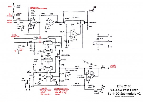
My goal in designing the E-mu 1100 was to bring out what I consider the elegant sound of the Moog ladder without the distortions caused by static non-linear transfer functions of other transistor amplifiers. One result of this approach is that rather than biasing the first ladder stage to allow for a ground-based exponential control current generator, I chose to offset the exponential generator above ground so that the first ladder stage has its bases (the signal input to the filter) biased at ground. This eliminates the need for any input signal level-shifting stage; it also makes it easy to DC couple the circuit.
As noted, I chose to bias the other ladder stages using diodes rather than a resistor ladder. This was done primarily to save current: the impedance of a diode at 3.3mA bias current is about 8 ohms; to get that same impedance with resistors, the bias network would draw 75mA. I chose to only use one diode per bias stage (causing the ladder transistors to operate fairly near saturation) because listening tests showed me there was virtually no audible difference from using two or three diodes per stage - in fact I recall liking the sound of the single diode a bit better than two. It also saved some parts!
Also as noted, the 100k/200 ohm input signal attenuator gives a lower that traditional signal level in the ladder, which means less distortion. But the E-mu modular was designed to handle 20V p/p signal levels, so the peak signal level at the ladder inputs are 40mV p/p, though the "standard" level was half that.
A couple of other things to note in the circuit before discussing the unique output stage: The 100pF capacitor in the Q feedback path compensates for other parasitic elements, causing the Q and oscillation level to remain fairly constant at high frequencies. The choice to use a PNP ladder was because I particularly liked the 2N4250 PNP small signal transistor - I can't tell whether this yielded an audible result because I never did a double-blind test to see if what I was hearing was real or not. Finally, you'll note that while the first (QD402) and last (QD102) transistor pairs in the ladder are matched monolithic pairs, the remaining (2N4350) transistors are not matched. This is because the dynamic emitter resistance (the R in the RC of the filter) of the transistors is set by the laws of physics as k*T/(q*Ie), which is NOT a function of "Is", the current that is matched for matched pairs. While there might be parasitic bulk emitter resistance or perhaps some other effects that could affect the ladder sound, hand matching the transistors would not cause these parameters to be matched, and I deemed any such effect to be too small to justify the (substantial) cost of using monolithic matched pairs in these locations.
The 1100 output stage was probably my first real analog circuit "invention" - a circuit that didn't build on one I'd been taught or seen elsewhere. To understand its operation and raison d'etre, first consider what a traditional PNP Moog ladder output stage looks like. Instead of the QD102, there would be another pair of PNP transistors (these WOULD need to be matched if the ladder is to be DC coupled), with their bases on the bias chain, their collectors to the negative supply, and their emitters connected to the last capacitor of the ladder. Also on those emitters would be the inputs to a high gain amplifier, which would boost the signal from ladder levels (40mV p/p full level) to output levels (20V p/p), a gain of 500.
I didn't like a number of things about this approach. First, such a high gain amplifier will be the primary source of noise in the module, and with my desire to use lower signal levels, this was problematic. Next, most such amplifiers practical in 1974 would be open loop and thus have significant distortion of exactly the kind I didn't want. Finally, the loading of the final PNP pair by the bias current of such an amplifier would limit the low frequency capabilities of the filter (I wanted to be able to filter control voltages, which required cutoffs as low as 0.1Hz).
This last problem could be solved by using a JFET input stage. Integrated JFET opamps were not available in 1974, but dual matched JFETS such as the IMF3958 were not too expensive. But JFETS have 10-20dB higher noise voltage that BJTs, so such a simple solution just exacerbated the noise problem.
I realized that the last ladder stage didn't need to use transistors; since the (traditionally) PNP collectors of this stage just dump their current to the negative supply, they might as well be diodes. And that meant they could either be NPN or PNP diode connected transistors (connecting base to collector). That was the first step in my insight.
I then realized that if I used NPN transistors for the last stage, and put a JFET unity gain buffer between the collector and base of each transistor, the impedance at the bases (which could be used as the point to drive the high gain amplifier) would be lowered by the loop gain, which would be large due to the current source nature of the ladder PNP and NPN collector outputs. This is exactly what is being done on the left had side of the ladder as drawn. You can think of it this way: The JFET buffer (the stack of two matched JFETS, one serving as a current source that sets the operating current of the other JFET to a value that gives zero volts gate-source offset) gets pulled by the output of the next to last ladder stage to exactly that voltage that produces the current of that side of the ladder to be sunk by the NPN. But that voltage will, of course, be the same voltage as what the diode (or PNP transistor emitter-base voltage) would be. But because the base of the NPN is driven by the buffer, in feedback, that point in the circuit will now be quite low in impedance.
Now for the trick part: I do the same thing on the right-hand side of the ladder, but this time I put a resistive attenuator (4.7k to 200 ohms) between the buffer and the NPN base. The same thing happens as above - the right-hand NPN base is forced by feedback to be the same voltage that would have appeared across a diode or PNP transistor output stage. But this time, the JFET buffer output must deviate 4700/200 = 23.5 times as much as that base to keep the feedback in balance. In other words, the NPN ladder transistor is also operating as an output amplifier. This has great noise and linearity benefits. Because that NPN transistor was in the circuit anyway, its noise was contributed as a ladder element anyway; having it operate as an amplifier adds essentially no more noise. And since the "noisy" JFET is operating at unity gain on a much higher level (+27.5dB) signal, its noise contribution now becomes negligible. Finally, since we are able to use feedback rather than an open-loop amplifier, any amplifier distortion is also reduced by the open loop gain factor.
All that remains is to boost the signal up to full level, using the uA748. You can see the gains add up - the signal input attenuator is 100k/200R; the output is 200R/4k7, then 4k7/100k.
Why the extra diode on the right side of the ladder? It adds 600mV bias voltage to the JFET buffer, which will now center the operating point of the right hand side of the 1nF final cap to the middle of the 3 diode drops allowed for that stage. Remember, we increased the gain on this side of the ladder, so now, while the signal at the base of the NPN is the ladder signal, on the NPN's collector instead of 40mV p/p. we'll see 940mV p/p. The diode keeps us from saturating either collector connected to this point.
Why is the capacitor only 1nF rather than 20nF? That's because since it's signal is 23.5 times bigger, the effective impedance at the collector of the NPN is 23.5 times smaller. So the ideal value for that capacitor should be 20nF/23.5 = 851pF. But I rounded up to 1nF because they were all +/-20% capacitors anyway!
I hope this people find this interesting, entertaining, and informative. For me, it's been a fun trip down memory lane.
--dave R |
|
|
Back to top
|
|
|
elektrouwe
Joined: May 27, 2012
Posts: 146
Location: Germany
|
| Posted: Tue Sep 27, 2016 1:34 pm Post subject:
|
|
|
| rossum wrote: | ... I'm ... delighted to provide details of the design.
|
wow, great to see you here, Dave & thanks a lot for the detailed information ! |
|
|
Back to top
|
|
|
Juan Bermúdez Costa
Joined: May 21, 2013
Posts: 2
Location: Barcelona
|
| Posted: Tue Sep 27, 2016 2:35 pm Post subject:
|
|
|
| rossum wrote: | Hi,
I'm pleased to see people are interested in how the circuit works, and am delighted to provide details of the design. |
I have always pleased a lot to understand the hows and whys of the electronics inside synthesizers. I enjoy it for 40 years.
I believe the analog design has a high percentage of creative art. An art misunderstood by the vast majority of synthesizers user's and many current builders...
I was fascinated by your very detailed explanation about your Lowpass Filter. Thanks for your wit and transparency.
If may I say, you are an ARTIST of electronics Dave. |
|
|
Back to top
|
|
|
varice

Joined: Dec 29, 2004
Posts: 961
Location: Northeastern shore of Toledo Bend
Audio files: 29
G2 patch files: 54
|
Posted: Tue Sep 27, 2016 9:08 pm Post subject:
Re: Dave Rossum Ladder Filter with PNP Transistors
Subject description: ROSSUM'S LADDER FILTER with PNP Transistors |
|
|
| Juan Bermudez Costa wrote: | | This is my restoration of Emu Low Pass 2100 old schematic with v2 1100 submodule.... In my opinion it is not simply a classic moog ladder network implemented with PNP transistors... |
Juan, thanks for posting this. I’m a big fan of the sound of the original Moog transistor ladder low pass filter. The many variations of the design are also very interesting. I had not seen this E-mu (Rossum) variant before.
And  to the electro-music.com forum to the electro-music.com forum 
_________________
varice
Last edited by varice on Tue Sep 27, 2016 9:49 pm; edited 1 time in total |
|
|
Back to top
|
|
|
varice
Joined: Dec 29, 2004
Posts: 961
Location: Northeastern shore of Toledo Bend
Audio files: 29
G2 patch files: 54
|
| Posted: Tue Sep 27, 2016 9:27 pm Post subject:
|
|
|
| rossum wrote: | Hi,
Dave Rossum here, the guy who actually created the E-mu 1100 Mk2 back in 1974. I'm pleased to see people are interested in how the circuit works, and am delighted to provide details of the design...
|
Dave, thank you for taking the time to give such a detailed explanation of your version of the Moog ladder filter. I appreciate that very much
And to the electro-music.com forum
_________________
varice |
|
|
Back to top
|
|
|
mosc
Site Admin

Joined: Jan 31, 2003
Posts: 18252
Location: Durham, NC
Audio files: 227
G2 patch files: 60
|
| Posted: Wed Sep 28, 2016 3:49 pm Post subject:
|
|
|
Hi Dave.
Great to see you see here on the e-m forum. It's been a long time. As best I can remember, your modular system in the 70s was the first polyphonic modular, preceding the Prophet 5. I remember interviewing you and playing your synthesizer on my KPFA radio show called Thin Aire. I think that may be the last time I saw you; too long.
Your circuits at that time were, and still are, superb.
_________________
--Howard
my music and other stuff |
|
|
Back to top
|
|
|
mosc
Site Admin
Joined: Jan 31, 2003
Posts: 18252
Location: Durham, NC
Audio files: 227
G2 patch files: 60
|
| Posted: Wed Sep 28, 2016 3:50 pm Post subject:
|
|
|
Juan, to electro-music.com. Thanks for posting.
_________________
--Howard
my music and other stuff |
|
|
Back to top
|
|
|
Paradigm X
Joined: Feb 15, 2011
Posts: 363
Location: Null and void
Audio files: 2
|
| Posted: Thu Sep 29, 2016 5:45 am Post subject:
|
|
|
wow. cool thread, thanks to OP for posting and obviously also to Dave Rossum for his brilliant explanation.
A bit (well a lot) over my head. But still very interesting.
Cheers |
|
|
Back to top
|
|
|
brock

Joined: May 26, 2011
Posts: 112
Location: Canada
|
| Posted: Thu Sep 29, 2016 9:41 pm Post subject:
|
|
|
This is a great thread. Thanks for posting Juan, and especially Dave for the response. It was all of interesting, entertaining, and informative.
Brock |
|
|
Back to top
|
|
|
Cfish

Joined: Feb 24, 2016
Posts: 477
Location: Indiana
|
| Posted: Tue Oct 11, 2016 3:10 pm Post subject:
|
|
|
I have 3 books open trying to understand everything just talked about. That is awesome.
I love analog and work to one day truly understand it.
I'm sure I will be referring back to this thread for years to come, and I am for sure building this filter.
How could I not try it with this vast array of knowledge at my fingertips. |
|
|
Back to top
|
|
|
|

 Forum index » DIY Hardware and Software » Developers' Corner