| Author |
Message |
Werebear

Joined: Nov 23, 2009
Posts: 63
Location: UK
|
|
|
Back to top
|
|
 |
Grumble

Joined: Nov 23, 2015
Posts: 1319
Location: Netherlands
Audio files: 30
|
 Posted: Thu Nov 03, 2016 11:18 pm Post subject: Posted: Thu Nov 03, 2016 11:18 pm Post subject:
|
  |
|
First question is why have a resistor in series with a current source? A current source is high impedance, so no need for this resistor. Besides that:using this resistor will lower the span voltage of your current source.
Second is how did you measure the tracking? I can't figure out what the impedance of the ribbon controller is, but if its high ( several 100k's) and you are measuring with a scope probe of 1meg (or something similar) that is in parallel with the ribbon controller, it is obvious that this will f#ck up your linearity... |
|
|
Back to top
|
|
|
Werebear
Joined: Nov 23, 2009
Posts: 63
Location: UK
|
| Posted: Fri Nov 04, 2016 5:40 am Post subject:
|
|
|
Hi Grumble
thanks for getting back. Been watching your keyboard controller thread.
I don't have a scope so forget about 1M probes. I have a DMM and all measurements are from that - not ideal but you work with what you've got.
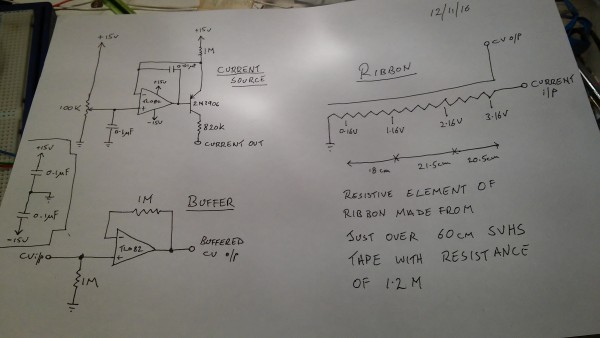
I did the maths, Iout = (Vsupply - Vref)/R2, after I had a think about what I wanted from the ribbon, which is three octaves with as linear a response as possible which I new would be difficult with such high resistive material. I measured the resistance of my ribbon at about 1.2M, from that calculated the current needed at 3V. I put that into the current source equation and solved for R2 which came out at 1M. I initially had a 2K trim in series with it but when I breadboarded it it did little if nothing. I tried this with the ribbon and got a squashed non-linear response with 0V to 1V at 9cm as opposed to something like 20cm on a 60cm ribbon. I remembered reading about adding resistance to pots to condition their response so tried it here and found by having the 820K in series with the ribbon it gave a more linear response with 0V to 1V now at 17cm - if you look at the drawing I made of the ribbon itself it will show the distance between the 1V increases. Ideally the response would be 0V - 1V covers 20cm of ribbon, 1V - 2V the next 20cm and 2v - 3V the final 20cm. I hope this makes sense!!!
As I said I'm happy with the results I got though a little unsure how I got them but my big problem is buffering the resulting CV. I've tried a couple of different op amps with the same results on each. When there is 0V on the non-inverting input the output is at 4V. When I touch the low end of the ribbon this drops to something closer to what I would expect, but as I move my finger up the ribbon the voltage increases but does not track the input, putting out much more than the input. I've used TL081 and an 071 with the same results.
I'm away this weekend so won't be able to play with it until next week but I intend to rebuild it using a dual amp and then using the second amp in the package to buffer the CV.
Thanks
Bear
_________________
I think I like it. Does it matter if I don't? |
|
|
Back to top
|
|
|
blue hell
Site Admin

Joined: Apr 03, 2004
Posts: 24513
Location: The Netherlands, Enschede
Audio files: 298
G2 patch files: 320
|
| Posted: Fri Nov 04, 2016 6:36 am Post subject:
|
|
|
At these impedances you would be picking up a lot of hum from your finger - which probably makes for some messy results.
Also with these impedances .. what is the input resistance of your DMM?
Your positional info seems off (roughly) by about 10% so my guess is that it is a 10 MOhm input on the DMM ...
_________________
Jan
also .. could someone please turn down the thermostat a bit.
 |
|
|
Back to top
|
|
|
Werebear
Joined: Nov 23, 2009
Posts: 63
Location: UK
|
| Posted: Sat Nov 12, 2016 9:43 am Post subject:
|
|
|
Hi
had a chance today to get back to this after a lot of googling and I think I've got it to work and work a little bit better. I read up a lot on op amp buffers and looked at other designs of ribbon controllers.
The first thing I found and hadn't thought about before is that when not touched the wiper is floating. Other designs have a resistor to ground for the wiper so I experimented there and found a 1M resistor does the job.
Secondly I read about op amp buffers sometimes needing a resistor in the feedback path to stabilise them and so I placed a resistor in the feedback path of my buffer. I also ditched the lm741 and used a tl084 in the vague hope that two amps in the same package might behave.
The result is that voltage out of the buffer is the same as voltage into the buffer. The current source is the same as I started with with the 820K in series with the ribbon.
Grumble - that resistance in series with the ribbon improves the linearity of the ribbon and including the 1M to ground on the wiper has also helped things along a bit. See the new drawing for positional info. Without the 820K the response was very non-linear.
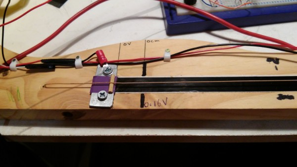
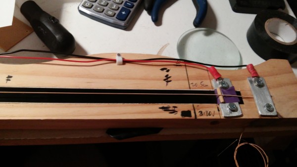
Blue Hell - not sure what you mean by 10% off? The bottom/left hand end of the ribbon is at ground but because of the mechanical construction of the ribbon it will never read 0V so I chose a low voltage of 0.16V - which is the closest I can get to 0V with my fat fingers and the tension on the string - and then looked at where the 1V increases where on the length of the ribbon. Look at the drawing and the photos to see this. As for the noise, yeah it's there. I actually do own a toy oscilloscope (DSO 138 - kit £13 off ebay) and the trace is not smooth. I hope some sort of insulator over the entire string/tape ensemble will help that.
So next will be a simple sample and hold which will take up the two remaining op amps in my tl 084.
Perhaps cart before horse but I don't currently have an oscillator to put this to and of course the whole thing will be moot when my Spectra Symbol 50cm 10K softpot arrives after being on back order forever. However I've learned a lot through this process.
Thank you for your input.
Jim Von Bear
| Description: |
|
| Filesize: |
1.53 MB |
| Viewed: |
403 Time(s) |
| This image has been reduced to fit the page. Click on it to enlarge. |
|
| Description: |
|
| Filesize: |
1.44 MB |
| Viewed: |
394 Time(s) |
| This image has been reduced to fit the page. Click on it to enlarge. |
|
| Description: |
|
| Filesize: |
1.23 MB |
| Viewed: |
380 Time(s) |
| This image has been reduced to fit the page. Click on it to enlarge. |
|
_________________
I think I like it. Does it matter if I don't? |
|
|
Back to top
|
|
|
Cfish

Joined: Feb 24, 2016
Posts: 477
Location: Indiana
|
| Posted: Sun Nov 13, 2016 5:07 pm Post subject:
|
|
|
Hi Jim.
Just wanted to say it was nice to see someone else post a hand drawn schematic. Thought I might be the only one who did that.
Nice looking project |
|
|
Back to top
|
|
|
Werebear
Joined: Nov 23, 2009
Posts: 63
Location: UK
|
| Posted: Mon Nov 14, 2016 3:44 am Post subject:
|
|
|
Hi Cfish
yep I'm that old but I suppose that I will have to learn the software at some point.
At this stage it's hardly a project but more a learning exercise in current source design and ribbon controllers. I began with the SVHS tape because that's what I had and that's what I've used in the past for Tim Escobedos synth sticks. I know it's not the ideal material but I've kinda got something that I can make work for now. In fact yesterday I turfed out a load of rubbish and found a VHSC tape which is slightly lower resistance than the SVHS so I going to try that and see what I get.
Plus I like the look and feel of the guitar string arrangement which I stole from John Simonton's ribbon controller design (from which I will also steal the gate generator and sample and hold) as it feels a bit trautonium. I've even emailed Trautonics Trautonium to ask about the strings they supply - I assume something like a cello string wound with constantan. All I'd need then is a metal strip to press the wire onto and I'm away. Though I bet they're not cheap.
Been watching your simple keyboard controller thread as well for another far distant project. I want to put together a toy mono synth for my nephew but I might cheat and get the DSP Synthesizers VCDM chip. Then all I need is the keyboard controller, a couple of LFOs, a couple of AR generators and we're away.
Thanks for the comments Cfish,
Jim
_________________
I think I like it. Does it matter if I don't? |
|
|
Back to top
|
|
|
Cfish
Joined: Feb 24, 2016
Posts: 477
Location: Indiana
|
| Posted: Mon Nov 14, 2016 6:51 am Post subject:
|
|
|
Old is a relative term. LOL
I like hand drawn. You don't loose them when the computer crashes.
Will be looking forward to your updates. |
|
|
Back to top
|
|
|
Cfish
Joined: Feb 24, 2016
Posts: 477
Location: Indiana
|
| Posted: Sat Nov 19, 2016 2:16 pm Post subject:
|
|
|
| Been tossing around the idea of trying your ribbon controller hooked to one of the schematics in the basic volt per octive keyboard thread. I think it has enough adjustment to be linear with the resistances you mentioned. |
|
|
Back to top
|
|
|
Werebear
Joined: Nov 23, 2009
Posts: 63
Location: UK
|
| Posted: Sun Nov 20, 2016 6:35 am Post subject:
|
|
|
Well at the moment I haven't had much opportunity to play with this further but I have been thinking along similar lines. I have been able to construct a new ribbon with the VHSc tape which has a resistance of 655K as opposed to 1.2M for the SVHS ribbon. This onlys needs a 270K resistor in series with it to give good (enough) linearity. The problem now lies in getting a gate from this. I've tried a comparator so far and at the high end of the ribbon I get a gate of 11V (+/-15V supply) but towards the bottom end of the ribbon it drops off quite sharply. The 11V gate stays the same for about 80% of the length of the ribbon but then drops off. I've also had no luck with a sample and hold using a MPF102 but I think that's because I dumbly mixed up drain and source!
I'm at the point where I think I want to change approach and look at putting the ribbon in the feedback path of an op amp as in the keyboard schematics from EFM and the one from Yves Ussons page that you've been discussing on that thread. I've done what I think are the right calculations:
Vout = -Rf/Rin x Vin
where the ribbon is Rf (ribbon + series resistor), Vin is -15V and Vout is my 3V for approx. 3 octaves. Solving this for Rin gives me 4.7M. I will include a trimmer in there as well to set voltage as it is done in the keyboard schematics.
However I've just had word from Sparkfun that my softpot is on the way but at the same time I want this to work. So I won't give up on this yet as I have loads of video tape but softpots are £20 plus each from America and I can't find a British supplier. Will report back.
_________________
I think I like it. Does it matter if I don't? |
|
|
Back to top
|
|
|
Werebear
Joined: Nov 23, 2009
Posts: 63
Location: UK
|
|
|
Back to top
|
|
|
Werebear
Joined: Nov 23, 2009
Posts: 63
Location: UK
|
|
|
Back to top
|
|
|
Werebear
Joined: Nov 23, 2009
Posts: 63
Location: UK
|
| Posted: Wed Nov 30, 2016 7:41 am Post subject:
|
|
|
Well I have to conclude that I'm going to give up on the VHSc ribbon controller for now. There are probably ways to make this work but they are beyond me at the moment.
I ended up building both a current source and a voltage source for the ribbon and trying them out with Synthmongers 40106 trig/ramp VCO. I use this as he suggests with a small cap and a 4040 frequency divider.
With a pot wired to +/-15V it gives a squarewave. When I added in the CV from the ribbon it tracked wonderfully but the distortion and noise where horrific as Blue Hell pointed out they would be and not at all what I wanted.
However it was a worthwhile experiment for me as I have learned a lot about current sources which will stand me in good stead.
Also I have begun to think about conductive plastics and how potentially easy it would be to manufacture them. I read an Instructable about manufacturing plastics from PVA glues and various filler powders such as talc. It would be easy to replace this with powdered carbon and then produce conductive strips for ribbon controllers either by casting long thin "blocks" or painting it onto a substrate. I will experiment with this but probably not soon.
In the meantime I will await the arrival of my softpot to carry on with this project.
Thanks to everyone for their input.
_________________
I think I like it. Does it matter if I don't? |
|
|
Back to top
|
|
|
|

 Forum index » DIY Hardware and Software » Developers' Corner


