| Front Page | Radio | Media | Forum | Wiki | Links |

and electronic music
|
|
Dedicated to
experimental electro-acoustic and electronic music |
|
|
|
 Forum index » DIY Hardware and Software Forum index » DIY Hardware and Software |
|
Designing a Sawtooth VCO
|
 
|
Moderators: jksuperstar, Scott Stites, Uncle Krunkus
Page 1 of 1 [4 Posts] |
View unread posts View new posts in the last week Mark the topic unread :: View previous topic :: View next topic |
| Author | Message | |||||||||||||||||||
|---|---|---|---|---|---|---|---|---|---|---|---|---|---|---|---|---|---|---|---|---|
|
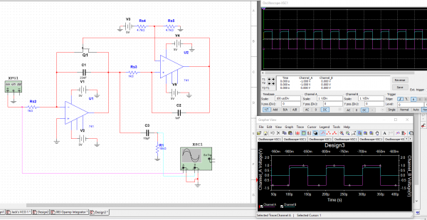
synthjakk
Joined: Feb 12, 2018 Posts: 20 Location: UK |
|
|||||||||||||||||||
|
|
||||||||||||||||||||
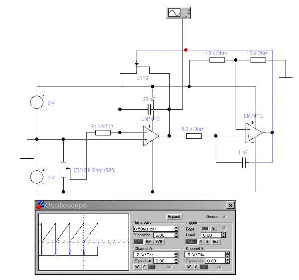
electrotech
 Joined: Apr 24, 2013 Posts: 47 Location: Ayrshire Scotland |
|
|||||||||||||||||||
|
|
||||||||||||||||||||
|
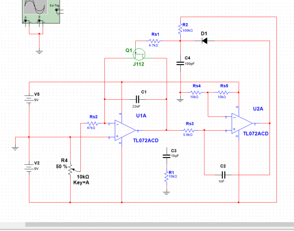
synthjakk
Joined: Feb 12, 2018 Posts: 20 Location: UK |
|
|||||||||||||||||||
|
|
||||||||||||||||||||
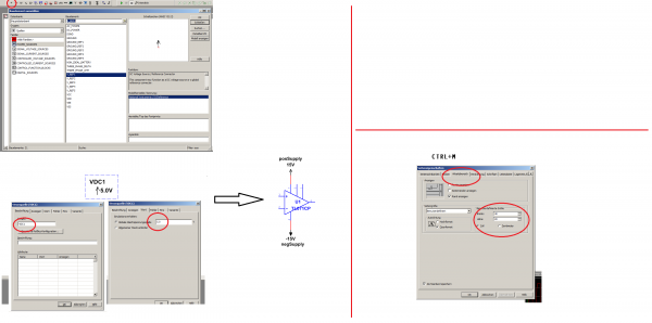
gabbagabi
 Joined: Nov 29, 2008 Posts: 652 Location: Berlin by n8 Audio files: 23 |
|
|||||||||||||||||||
|
|
||||||||||||||||||||
|
|
Moderators: jksuperstar, Scott Stites, Uncle Krunkus
Page 1 of 1 [4 Posts] |
View unread posts View new posts in the last week Mark the topic unread :: View previous topic :: View next topic |
|
Forum index » DIY Hardware and Software |
|
You cannot post new topics in this forum You cannot reply to topics in this forum You cannot edit your posts in this forum You cannot delete your posts in this forum You cannot vote in polls in this forum You cannot attach files in this forum You can download files in this forum |