| Author |
Message |
PHOBoS

Joined: Jan 14, 2010
Posts: 5881
Location: Moon Base
Audio files: 709
|
 Posted: Wed Jun 13, 2018 6:24 am Post subject:
KORG DW6000 hardware controller with Arduino nano Posted: Wed Jun 13, 2018 6:24 am Post subject:
KORG DW6000 hardware controller with Arduino nano
Subject description: sending sysex commands to control parameters |
  |
|
continuing from this thread.
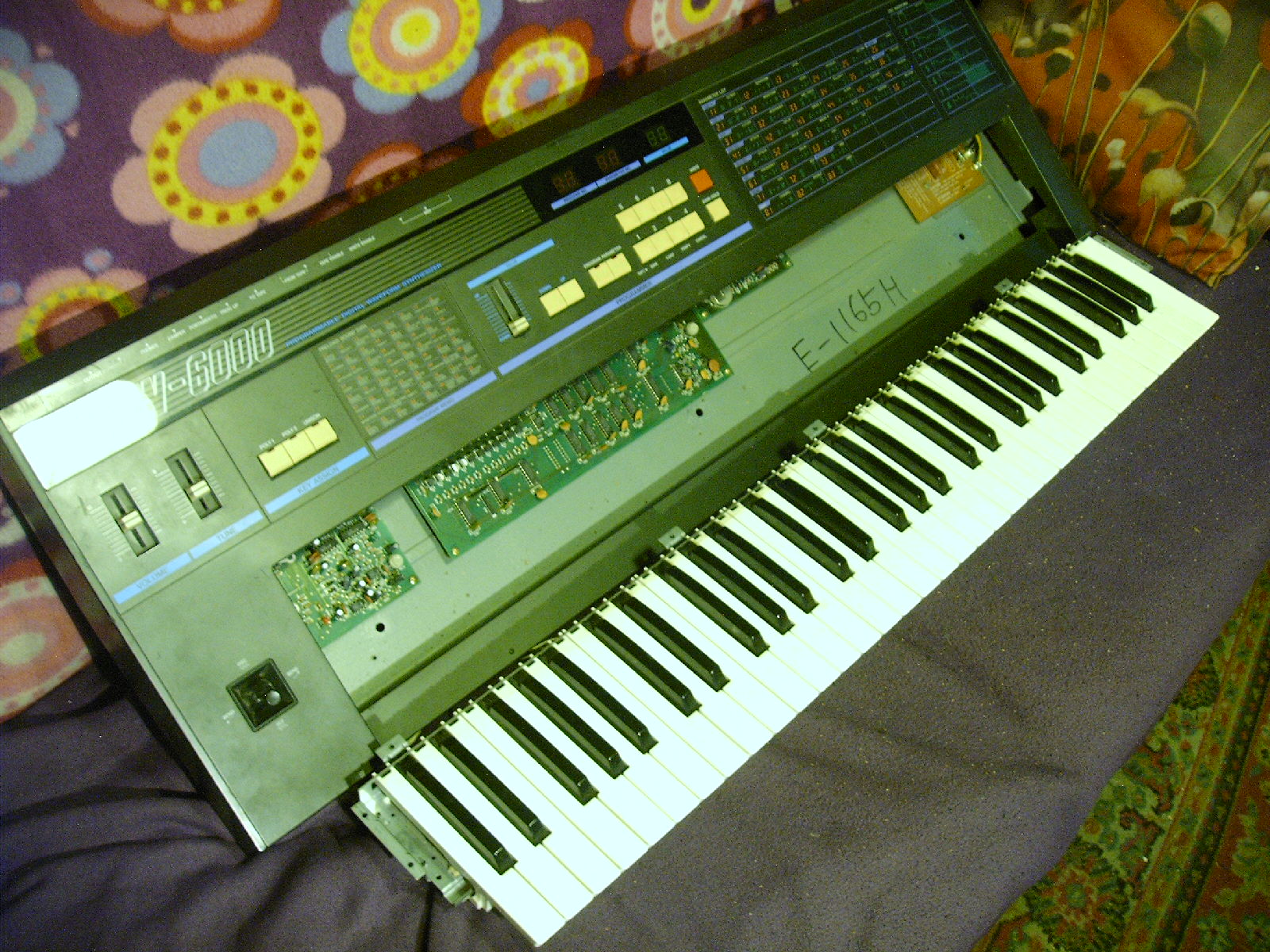
I have a KORG DW6000 synth which is pretty nice but there is something I don't like about it. It has 34 adjustable parameters
(not including midi setup and "key assign" modes) but only one control for them and some buttons to select which parameter to adjust.
Since I am used to modular synths with seperate controls for everything I don't find this very practical. It's also not very intuitive
to make adjustments since there is no visual representation of the current settings, unless you select a parameter and then it shows
the setting (a number) on a LED display. I think if it had a graphical display so you could see all the settings at once it would already
be an improvement. Luckily there is a way to adjust the parameters by using sysex commands and my goal is to make a hardware
controller to do just that.
Since I am using an Arduino I made a seperate thread for it in this section of the forum as there might be some things that could be
useful if someone wants to do a similar thing. So here I will post my progress, probably some snippets of code and sketches, ideas I
get along the way, problems I run into, etc. There are some other projects I am working on so I don't know how long it will take me
to finish this as I will probably take some breaks from it in between.
note that although I am pretty new to arduino's I do have some experience with PICs (using PIC basic) html and javascript so I am
not completely unfamiliar with writing code, that doesn't mean I am very good at it though. As for midi, I rarely use it so I don't
know the commands but I have some ideas about how it works and information about it is pretty easy to find online. And if I get really
stuck I could ask DrSteve (aka MusicMan11712) who seems to know a lot about it.
here's a photo of the synth itself (keybed was seperate when I got it).
_________________
"My perf, it's full of holes!"
http://phobos.000space.com/
SoundCloud BandCamp MixCloud Stickney Synthyards Captain Collider Twitch YouTube |
|
|
Back to top
|
|
 |
PHOBoS
Joined: Jan 14, 2010
Posts: 5881
Location: Moon Base
Audio files: 709
|
| Posted: Wed Jun 13, 2018 7:28 am Post subject:
|
|
|
so, what do I want ?
The bare mimimum would be a small box with controls for each parameter which I can place on top of the synth and plug into its MIDI input.
The controls are made with potentiometers configured as a voltage divider connected to analog input pin(s) of the Arduino. The Arduino will
read the control values and send out the corresponding midi message.
Since I am already using voltages to control the parameters the next step would be to add external inputs for CVs from my modular synths.
I could actually make the whole controller into a synth module, but it might get a bit too large for that and I am also not sure if it would be very
practical to use. It would make it easier to patch though. I will try to keep it simple so no extra controls for external inputs, probably no buffers
either. The easiest thing would be to connect the external inputs directly to the control pots using sockets that will normalize it to 5V when nothing
is plugged in. So when an external CV is connected they will function as attenuators for it.
A CV input to control the actual pitch would be nice too. That means I could use the synth as a VCO (I am not much of a keyboard player anyway).
I can't just sweep the frequency (at least not to my knowledge) but I could convert the voltage into appropriate MIDI commands to simulate
pressing the keys. I could actually add a quantizer with different scales. I am not sure yet how to handle Note On/Off though. If I treat it like a
standard monophonic VCO I could just send Note On/Off messages when the pitch changes but an external gate input might make more sense.
However, it is a 6-note polyphonic synth so it would be a bit of a waste if I didn't make use of that. Maybe 6 CV/Gate inputs ?
Some kind of sequencer/arpeggiator ? It's pretty easy to make a midisequencer with an arduino but how to program/control it ? I could use the
parameter controls for this as well so in sequencer mode they adjust the notes and in control mode the parameters. However, there is a downside
to this method (at least when using pots and not rotary encoders). Whenever you use the sequencer mode you lose the visual representation of
the parameter settings. Code wise it would be possible to add some sort of catch-up so when you adjust a parameter it doesn't change untill you pass
the current setting. A better way would be to use the actual keys on the synth but that means reading MIDI aswell. It's possible but might get a bit
tricky to code (at least for me).
A small LCD display for parameter settings. I think this could be useful to display things like selected waveform and octave, Also useful for quantizer
or sequencer info. If I do add one I will probably come up with some more uses for it.
Storing patches, sequences and other things. The DW6000 can store 64 different patches/voices but I could store them in the arduino.
That just reminds me of another thing. It is possible to select voices stored in the synth through midi too, maybe add a contol for that as well.
Of course you will again lose the visual representation if you'd switch to a different voice.
I will probably get some more ideas along the way and any suggestions are welcome too of course 
_________________
"My perf, it's full of holes!"
http://phobos.000space.com/
SoundCloud BandCamp MixCloud Stickney Synthyards Captain Collider Twitch YouTube
Last edited by PHOBoS on Sat Feb 05, 2022 6:31 am; edited 1 time in total |
|
|
Back to top
|
|
|
PHOBoS
Joined: Jan 14, 2010
Posts: 5881
Location: Moon Base
Audio files: 709
|
| Posted: Wed Jun 13, 2018 11:25 am Post subject:
|
|
|
hardware:
The main core will be an Arduino Nano 3 (actually it's just a cheap chinese clone).
As mentioned I want to use potentiometers to control parameters but I am not sure yet if I want to do this for all parameters. There are
actually already 3 parameters for which I will use switches:
bend VCF on/off: determines if the joystick is used to change the VCF cutoff frequency. (I am not even sure if I will add a control for this)
VCF eg polarity: determines if the signal from the envelope generator for the VCF is inverted or not.
Chorus on/off: self-explanatory.
There are some more parameters that only have a limited amount of settings, like waveform, octave, VCF keyboard tracking, interval and
detune. There is no problem with using a pot for these and I can just design the front in such a way that it's easy to see what the setting is but
another possibility would be to use (rotary) switches with a resistor network. However, I wouldn't be able to use them as attenuators for CVs.
I am also not sure yet if I want to use all rotary pots or use sliders for some paramaters. Envelope generators make much more sense with
sliders and there might be some other parameters for which they are more suitable as well. Downside of sliders is that they are a PITA when
making a frontpanel (especially from MDF), finding the right knobs can be tricky and they are slightly more expensive and harder to obtain.
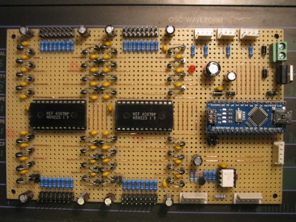
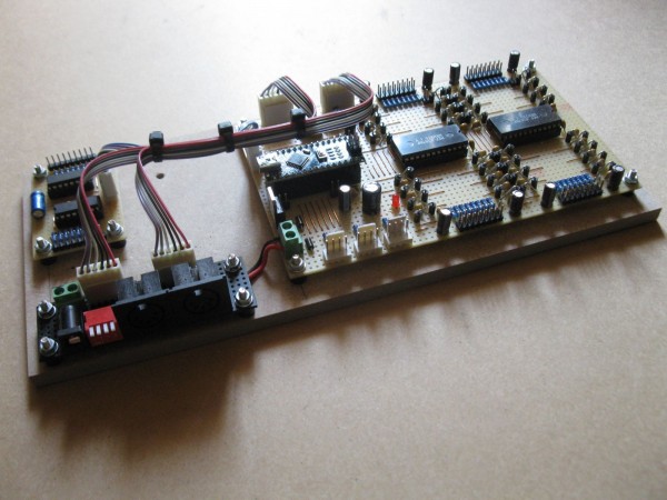
To be able to use so many analog controls I use multiplexers, it can only read 1 control at a time anyway. At the moment I've opted for 2x
4067 which is a 16 to 1 mux. That gives me a maximum of 32 analog inputs while using only 2 analog inputs on the arduino and 4 digital outputs.
I could use 4x 4051 (8 to 1 mux) which is a bit easier to obtain and because it has an inhibit pin I would only need 1 analog input on the arduino.
It would require 2 additional digital outputs though but only needs 3 control bits, so in total it requires 1 analog input and 5 digital ouputs.
I made a test board for it with trimpots which makes it easier to test the code I am writing. I only had 10 pots left though but more are ordered.
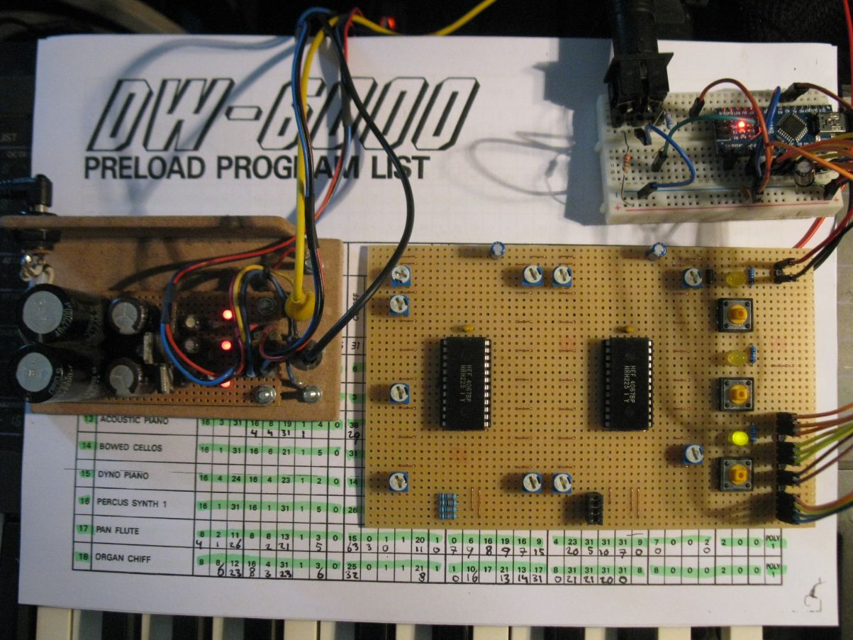
As you can see it also has 3 pushbuttons and LEDs. I could use toggle switches and leave out the LEDs which would make the code a bit simpler.
The advantage of pushbuttons is that you can set and change the state in code and they can be configured as momentary or latching. It's also
possible to combine buttons to do different things. (like pressing 1 & 2 at the same time will enter a different mode).
At the moment the switches (and LEDs) are all wired directly to digital input pins on the Arduino. However, I still have 1 unused analog input on
one of the muxes as I only need 31* analog controls. Earlier today I was thinking that I could just use the switches in combination with a resistor
network and connect it to the mux. That would save me 3 digital input pins on the arduino and it would be easy to add more buttons. For the
LEDs it might be possible to use the control lines for the muxes and one additonal output if I add some extra hardware.
If I add CV inputs I need some form of protection as the voltage levels can exceed 5V and also be negative. Grumble did some tests supplying
voltages to in- and outputs and posted the results here. According to those tests a 1K resistor in series might be sufficient. However the signals
first pass through a mux which also needs to be protected and I don't think simply using a resistor would be ok. Together with some diodes to clip
the voltage to the supply rails it could be fine though.
For the normalized sockets it would be easiest to connect them directly to +5V, but when you plug something in there is a moment where the tip
of the connector would be connected to +5V and thus whatever output is connected on the other side of the cable would be as well. In an ideal
world outputs are protected and this wouldn't cause any problems but better not to count on that. Adding a resistor in series should prevent any
problems but also causes a voltage drop in combination with the potentiometers. I could use a slightly higher voltage instead of +5V to compensate
for this or add buffers before the potentiometers. Another possibility is to make some adjustments in the code, I think it's even possible to adjust
the ADC voltage range itself.
I also need a powersupply. I'd like to make it so it all runs on +5V or maybe higher but at least a single supply. I could use a seperate supply for this
but maybe I can tap into the DW6000 PSU and add a connector for it on the back. It shouldn't be needing a lot of current anyway.
* there is 1 more parameter that I didn't implement which is the "Key Assign" setting. It already has 3 seperate buttons on the synth for this and
I don't think there would be much use in adding an external control for it.
_________________
"My perf, it's full of holes!"
http://phobos.000space.com/
SoundCloud BandCamp MixCloud Stickney Synthyards Captain Collider Twitch YouTube
Last edited by PHOBoS on Thu Jun 14, 2018 1:45 pm; edited 2 times in total |
|
|
Back to top
|
|
|
PHOBoS
Joined: Jan 14, 2010
Posts: 5881
Location: Moon Base
Audio files: 709
|
| Posted: Wed Jun 13, 2018 2:08 pm Post subject:
|
|
|
Before I could really do anything I first needed to add a midi output to the arduino. I followed along with this video, tested with
the example code and that worked fine. Next I had to figure out what messages I needed to send to change the parameters.
(note that when I mention the manual I am refering to the DW6000 owners manual which can be found here)
In the midi implementation section of the manual there are bytes and descriptions for all the MIDI messages but it doesn't really
say how to use them. It's probably something standard but that's where my knowledge of MIDI is lacking. I found some information
here that helped me get further:
| Quote: | First you have to declare a sysex array, for example
| Code: | | byte sysexArray[14] = {F0, 43, 10, 26, 02, 06, 01, 00, 1F, 01, 78, 00, 00, F7}; |
and then you send that array with:
| Code: | | MIDI.sendSysEx(14, sysexArray, true); |
|
This made me realize that I'd probably have to send all the bytes mentioned in the manual for parameter change.
| Quote: | 11110000 EXCLUSIVE
01000010 KORG ID 42H
00110000 FORMAT ID 30H
00000100 DW-6000 ID o4H
01000001 PARAMETER CHANGE 41H
0vvvvvvv PARAMETER OFFSET (See DW-6000 BIT MAP)
0vvvvvvv PARAMETER VALUE (See DW-6000 BIT MAP)
11110111 EOX |
Initially this still didn't work untill I found out I had to change a setting on the DW6000 itself to enable it for sysex messages. After this
I could actually change the parameters.  I posted a test sketch here which repeatedly sweeps the filter cutoff frequency up/down. I posted a test sketch here which repeatedly sweeps the filter cutoff frequency up/down.
here's a snippet of code that declares the sysex array: | Code: | // KORG DW6000 parameter change bytes
const byte exclusive = 0xF0;
const byte korg_id = 0x42;
const byte format_id = 0x30;
const byte dw6000_id = 0x04;
const byte param_change = 0x41;
const byte eox = 0xF7;
byte param_offset = 5; // selected parameter (5 = filter cutoff frequency)
byte param_value = 0; // value for selected parameter
byte sysexArray[] = {exclusive, korg_id, format_id, dw6000_id, param_change, param_offset, param_value, eox}; |
As you can see I didn't put the values directly in the array as I think it's easier to understand this way.
(note I am now using #define instead of const byte)
_________________
"My perf, it's full of holes!"
http://phobos.000space.com/
SoundCloud BandCamp MixCloud Stickney Synthyards Captain Collider Twitch YouTube
Last edited by PHOBoS on Thu Jun 14, 2018 1:52 pm; edited 1 time in total |
|
|
Back to top
|
|
|
MusicMan11712
Joined: Aug 08, 2009
Posts: 1082
Location: Out scouting . . .
|
| Posted: Thu Jun 14, 2018 1:21 pm Post subject:
|
|
|
| PHOBoS wrote: | | As you can see I didn't put the values directly in the array as I think it's easier to understand this way. |
I can think of another good reason--flexibility and re-usability of code. For example, you could have switches or knobs or anything to assign the sliders/pots and depending on those setting, you just change the id of the parameter. |
|
|
Back to top
|
|
|
PHOBoS
Joined: Jan 14, 2010
Posts: 5881
Location: Moon Base
Audio files: 709
|
| Posted: Thu Jun 14, 2018 1:32 pm Post subject:
|
|
|
yep, I am actually constantly keeping that in mind while writing the code.
here are some parts from what I have at the moment which is done like that exactly for this reason.
| Code: | // ******************************************************************************************************
// * KORG DW6000 SETUP *
// ******************************************************************************************************
// KORG DW6000 parameter change values (from manual)
#define exclusive 0xF0
#define korg_id 0x42
#define format_id 0x30
#define dw6000_id 0x04
#define param_change 0x41
#define eox 0xF7
// KORG DW6000 parameter offset values (from manual)
#define bend_OSC_offset 0
#define port_time_offset 1
#define OSC1_level_offset 2
#define OSC2_level_offset 3
#define noise_level_offset 4
#define cutoff_offset 5
#define resonance_offset 6
#define VCF_env_int_offset 7
#define VCF_env_attack_offset 8
#define VCF_env_decay_offset 9
#define VCF_env_break_offset 10
#define VCF_env_slope_offset 11
#define VCF_env_sustain_offset 12
#define VCF_env_release_offset 13
#define VCA_env_attack_offset 14
#define VCA_env_decay_offset 15
#define VCA_env_break_offset 16
#define VCA_env_slope_offset 17
#define bend_VCF_offset 18
#define VCA_env_sustain_offset 18
#define OSC1_octave_offset 19
#define VCA_env_release_offset 19
#define OSC2_octave_offset 20
#define mod_gen_freq_offset 20
#define VCF_kbd_track_offset 21
#define mod_gen_delay_offset 21
#define VCF_env_polarity_offset 22
#define mod_gen_OSC_offset 22
#define chorus_offset 23
#define mod_gen_VCF_offset 23
#define OSC1_waveform_offset 24
#define OSC2_waveform_offset 24
#define OSC2_interval_offset 25
#define OSC2_detune_offset 25
// *************************************************************************************************
// add id numbers for parameters (DO NOT ALTER!) [use CONTROLS SETUP to change function of controls]
#define OSC1_octave 0
#define OSC1_waveform 1
#define OSC1_level 2
#define OSC2_octave 3
#define OSC2_waveform 4
#define OSC2_level 5
#define OSC2_interval 6
#define OSC2_detune 7
#define noise_level 8
#define VCA_env_attack 9
#define VCA_env_decay 10
#define VCA_env_break 11
#define VCA_env_slope 12
#define VCA_env_sustain 13
#define VCA_env_release 14
#define port_time 15
#define VCF_kbd_track 16
#define VCF_env_int 17
#define VCF_env_attack 18
#define VCF_env_decay 19
#define VCF_env_break 20
#define VCF_env_slope 21
#define VCF_env_sustain 22
#define VCF_env_release 23
#define cutoff 24
#define resonance 25
#define mod_gen_freq 26
#define mod_gen_delay 27
#define mod_gen_OSC 28
#define mod_gen_VCF 29
#define bend_OSC 30
#define bend_VCF 31
#define VCF_env_polarity 32
#define chorus 33
// ****************************************************************************************************** |
| Code: | // ******************************************************************************************************
// * CONTROLS SETUP *
// ******************************************************************************************************
control[0] = OSC1_octave;
control[1] = OSC1_waveform;
control[2] = OSC1_level;
control[3] = OSC2_octave;
control[4] = OSC2_waveform;
control[5] = OSC2_level;
control[6] = OSC2_interval;
control[7] = OSC2_detune;
control[8] = noise_level;
control[9] = VCA_env_attack;
control[10] = VCA_env_decay;
control[11] = VCA_env_break;
control[12] = VCA_env_slope;
control[13] = VCA_env_sustain;
control[14] = VCA_env_release;
control[15] = port_time;
control[16] = VCF_env_int;
control[17] = VCF_env_attack;
control[18] = VCF_env_decay;
control[19] = VCF_env_break;
control[20] = VCF_env_slope;
control[21] = VCF_env_sustain;
control[22] = VCF_env_release;
control[23] = VCF_kbd_track;
control[24] = cutoff;
control[25] = resonance;
control[26] = mod_gen_freq;
control[27] = mod_gen_delay;
control[28] = mod_gen_OSC;
control[29] = mod_gen_VCF;
control[30] = bend_OSC;
control[31] = VCF_env_polarity;
control[32] = bend_VCF;
control[33] = chorus;
// ******************************************************************************************************
// create array with parameter offset values (DO NOT ALTER!)
param_offsets[OSC1_octave] = OSC1_octave_offset;
param_offsets[OSC1_waveform] = OSC1_waveform_offset;
param_offsets[OSC1_level] = OSC1_level_offset;
param_offsets[OSC2_octave] = OSC2_octave_offset;
param_offsets[OSC2_waveform] = OSC2_waveform_offset;
param_offsets[OSC2_level] = OSC2_level_offset;
param_offsets[OSC2_interval] = OSC2_interval_offset;
param_offsets[OSC2_detune] = OSC2_detune_offset;
param_offsets[noise_level] = noise_level_offset;
param_offsets[VCA_env_attack] = VCA_env_attack_offset;
param_offsets[VCA_env_decay] = VCA_env_decay_offset;
param_offsets[VCA_env_break] = VCA_env_break_offset;
param_offsets[VCA_env_slope] = VCA_env_slope_offset;
param_offsets[VCA_env_sustain] = VCA_env_sustain_offset;
param_offsets[VCA_env_release] = VCA_env_release_offset;
param_offsets[port_time] = port_time_offset;
param_offsets[VCF_kbd_track] = VCF_kbd_track_offset;
param_offsets[VCF_env_int] = VCF_env_int_offset;
param_offsets[VCF_env_attack] = VCF_env_attack_offset;
param_offsets[VCF_env_decay] = VCF_env_decay_offset;
param_offsets[VCF_env_break] = VCF_env_break_offset;
param_offsets[VCF_env_slope] = VCF_env_slope_offset;
param_offsets[VCF_env_sustain] = VCF_env_sustain_offset;
param_offsets[VCF_env_release] = VCF_env_release_offset;
param_offsets[cutoff] = cutoff_offset;
param_offsets[resonance] = resonance_offset;
param_offsets[mod_gen_freq] = mod_gen_freq_offset;
param_offsets[mod_gen_delay] = mod_gen_delay_offset;
param_offsets[mod_gen_OSC] = mod_gen_OSC_offset;
param_offsets[mod_gen_VCF] = mod_gen_VCF_offset;
param_offsets[bend_OSC] = bend_OSC_offset;
param_offsets[bend_VCF] = bend_VCF_offset;
param_offsets[VCF_env_polarity] = VCF_env_polarity_offset;
param_offsets[chorus] = chorus_offset;
|
_________________
"My perf, it's full of holes!"
http://phobos.000space.com/
SoundCloud BandCamp MixCloud Stickney Synthyards Captain Collider Twitch YouTube |
|
|
Back to top
|
|
|
PHOBoS
Joined: Jan 14, 2010
Posts: 5881
Location: Moon Base
Audio files: 709
|
| Posted: Mon Jun 18, 2018 7:16 am Post subject:
|
|
|
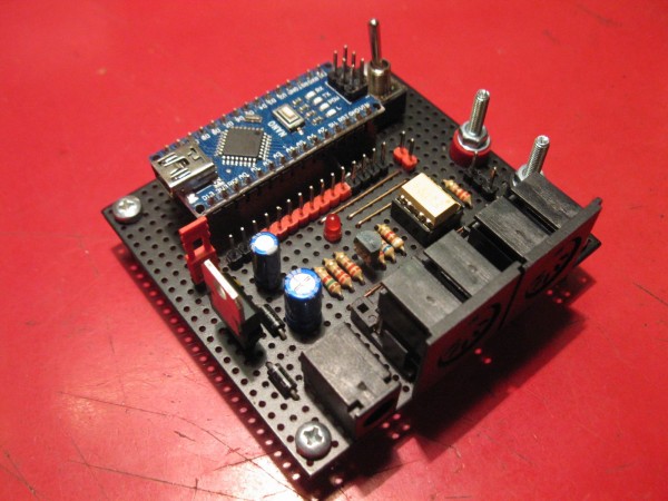
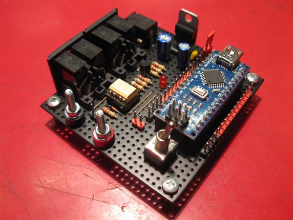
I made a test board for MIDI in & out + power. I haven't tested the input yet though. I also looked into the possibility of powering
the controller from the DW6000. The schematic is included in the service manual and the powersupply actually has 3x 5Volt
regulators. However I think it is better to just take the raw DC (11V) and built a seperate regulator in the controller. This way
I could also use an external DC supply if I'd want to.
I also changed the button setup to use an analog pin. Initially I used an R2R but the voltages I got out were not evenly spaced.
I calculated them and what I measures actually seemed to be correct which I found rather confusing. Untill I realized that an
R2R needs high and low signals, while the buttons can only provide a high signal. So I had to resort to a different setup.
| Description: |
|
| Filesize: |
249.91 KB |
| Viewed: |
877 Time(s) |
| This image has been reduced to fit the page. Click on it to enlarge. |
|
| Description: |
|
| Filesize: |
270.48 KB |
| Viewed: |
875 Time(s) |
| This image has been reduced to fit the page. Click on it to enlarge. |
|
_________________
"My perf, it's full of holes!"
http://phobos.000space.com/
SoundCloud BandCamp MixCloud Stickney Synthyards Captain Collider Twitch YouTube |
|
|
Back to top
|
|
|
PHOBoS
Joined: Jan 14, 2010
Posts: 5881
Location: Moon Base
Audio files: 709
|
| Posted: Thu Jun 28, 2018 10:46 am Post subject:
|
|
|
So far it all seems to be working and I have been thinking about other things to add. I did already add a random patch function
which creates random values for all parameters at the push of a button. A lot of times the results aren't that useful but it has
already created some nice patches.
I will probably leave at that though. It's nice to have an arpegiator or sequencer and I have been experimenting with one seperatly
but I think that the most useful method would be to just add a MIDI input to the controller and merge the values together in code.
This way the controller does all I need it to do and I can hook up another midi controller for sequencing or other things.
There is an example code with a midi merger included in the midi library. Looks very simple and I can probably adjust it to make use
of it, if I can find out how or rather why it works. So I have to figure out what the used comands do. I did read somewhere that when
using the library MIDI input signals are send to the MIDI output by default so that's probably useful. I might get rid of the library all
together though which I didn't know was possible untill steve mentioned something about me using it. But first I will mess around a bit
with reading midi signals and for that I'll probably have to solder a second cable.
_________________
"My perf, it's full of holes!"
http://phobos.000space.com/
SoundCloud BandCamp MixCloud Stickney Synthyards Captain Collider Twitch YouTube |
|
|
Back to top
|
|
|
PHOBoS
Joined: Jan 14, 2010
Posts: 5881
Location: Moon Base
Audio files: 709
|
| Posted: Thu Jun 28, 2018 4:44 pm Post subject:
|
|
|
I soldered a second midi cable, did a test and, after removing a solderbridge  , that worked. , that worked.
I actually got it working together wth the controller with only a single line of code, at least when using the midi library.
Not sure if it is entirely correct but I played some midifiles from my PC and could adjust parameters while it was playing.
I also just did a test without the library. So far the controller part works and that was actually pretty easy to do.
The merger part will probably get a bit more tricky though.
_________________
"My perf, it's full of holes!"
http://phobos.000space.com/
SoundCloud BandCamp MixCloud Stickney Synthyards Captain Collider Twitch YouTube |
|
|
Back to top
|
|
|
PHOBoS
Joined: Jan 14, 2010
Posts: 5881
Location: Moon Base
Audio files: 709
|
| Posted: Mon Jul 02, 2018 2:53 pm Post subject:
|
|
|
So far it is mostly working.
I can change parameters with the controller and I can also send thru external midi messages without anything weird happening. Only messages
recognized by he DW6000 are let thru the rest is ignored and some sysex messages are ignored as well. I am thinking about adding some DIP
switches for certain contol messages, like program change, so I can enable/disable the thru function for those.
But now I have run into a little problem regarding the key assign parameter. Key assign can be selected to be Poly1, Poly2 or Unison and because
there are already 3 dedicated buttons for this on the synth I was not planning on adding these to the controller aswell. It's also not something I am
likely to change remotely so I could ignore it completely. However, here's the problem. Some parameters share a value byte in the SysEx messages.
For example to change the "OSC2 Octave" parameter or the "Modulation Delay" parameter the same SysEx message has to be send. The only
difference is that bit 5 and bit 6 set the value for "OSC2 Octave" while bits 4 to 0 set the value of the "Modulation Delay". This is taken care of in the
code as all values are stored seperately and only merged together before being send. So if I'd adjust the control for "Osc2 Octave" it looks up the
stored value for "Modulation Delay" and merges the too.
"Assign mode" also shares a byte with "Bend Osc" (the range of the joystick or bend CC). So when I change the "Bend Osc" value it looks up the
stored "Assign mode" value. However, since there is no control for it its value never changes (at the moment I load a factory preset on startup which
also sets the assign mode to a certain value). This is all fine untill I choose a different assign mode on the synth. The controller has no way of knowing
it has changed so when I adjust the "Bend Osc" value it also sets the "Assign mode" value back to the stored value, which can differ from what the
synth has been set too.
I have some options:
- ignore it.
- add some buttons or a pot for assign mode (and never use the buttons on the synth).
- leave out the control for "Bend Osc" as well. It doesn't seem that useful to have a control for it. If I want to use the joystick I can easily adjust the
range on the synth itself and I don't think it would be something I adjust a lot.
- somewhat silly but I mention it anyway: add another midi input connected to the output from the synth so it can read parameter values adjusted on
the synth. It would mean I can always adjust values on the synth itself without running into any problems.
At the moment I think that just leaving out the "Bend Osc" control as well is the best option.
Something else I want to do is convert some external CC messages to sysex messages. This way I could control parameters like filter cutoff and
resonance with any standard midi sontroller.
I've also started on a calibration routine for the buttons. Since the buttons are connected to a resistor network the values might be a bit different
when I make the controller because of tolerances in the components. For the test setup I wrote a seperate program that printed the values when I
pressed one or more buttons and I copied those to the controller code. But I might aswell built in a routine that can be accessed when a button is
held on startup. It can't trigger the buttons itself though so it is still a manual process but the values are automatically stored in EEPROM for use later
on. At least that's the idea. Of course it should only be needed once but as long as I am not short on memory it seems like a useful addition.
_________________
"My perf, it's full of holes!"
http://phobos.000space.com/
SoundCloud BandCamp MixCloud Stickney Synthyards Captain Collider Twitch YouTube |
|
|
Back to top
|
|
|
PHOBoS
Joined: Jan 14, 2010
Posts: 5881
Location: Moon Base
Audio files: 709
|
| Posted: Wed Jul 04, 2018 6:42 am Post subject:
|
|
|
CC message to SysEx message is working too now
I also incorporated a catch-up function for the controls to prevent jumps in values. So when a parameter value is changed by
something else than a control (could be external midi, or by pressing the random patch button) the control first has to be rotated
to the point it catches up with the new value before actually changing it. For example if I would adjust the cutoff frequency to 50%
with the control (potentiometer) and then change it remotely to 25% the control first has to be rotated untill it is 25% (or less) before
it will have an effect on the cutoff frequency.
I did a test playing a midi file of Beethoven's Sonata No.14 (better known as Moonlight Sonata), the 3rd Movement* and it didn't seem
to have any problems keeping up while I adjusted controls at the same time. I might be a bit difficult to hear dropped notes though but
I didn't notice any.
* if you are not familair with it: here's a youtube link
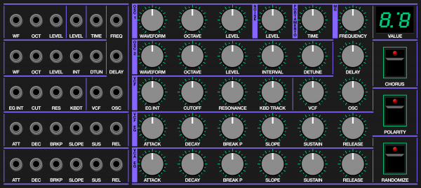
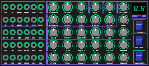
Feature creep is continuing as I am now considering adding a 2-digit numeric LED display to show values when they are adjusted.
The dots on the display could be used in conjunction with the catch-up function so that if the parameter value is lower than the control value
the left dot lights up, and if it is higher the right dot lights up. This way I can quickly see in which direction I'd have to rotate the control.
I do only have 4 digital in/out pins left on the arduino though and was thinking of using those for DIP switches but I could use analog pins
for those too. So I did a quick search to see if there is anything you have to keep in mind when using an analog pin for a digital input
(wouldn't really know why though except maybe speed) and discovered that the analog pins can be used as regular digital in/out pins.
The only thing to watch out for it that for some arduino models (incl the Nano I am using) A6 & A7 can not be used as digital pins.
_________________
"My perf, it's full of holes!"
http://phobos.000space.com/
SoundCloud BandCamp MixCloud Stickney Synthyards Captain Collider Twitch YouTube |
|
|
Back to top
|
|
|
ixtern
Joined: Jun 25, 2018
Posts: 145
Location: Poland
|
| Posted: Mon Jul 09, 2018 3:56 am Post subject:
|
|
|
| PHOBoS wrote: |
Feature creep is continuing as I am now considering adding a 2-digit numeric LED display to show values when they are adjusted.
The dots on the display could be used in conjunction with the catch-up function so that if the parameter value is lower than the control value
the left dot lights up, and if it is higher the right dot lights up. This way I can quickly see in which direction I'd have to rotate the control.
I do only have 4 digital in/out pins left on the arduino though and was thinking of using those for DIP switches but I could use analog pins
for those too. So I did a quick search to see if there is anything you have to keep in mind when using an analog pin for a digital input
(wouldn't really know why though except maybe speed) and discovered that the analog pins can be used as regular digital in/out pins.
The only thing to watch out for it that for some arduino models (incl the Nano I am using) A6 & A7 can not be used as digital pins. |
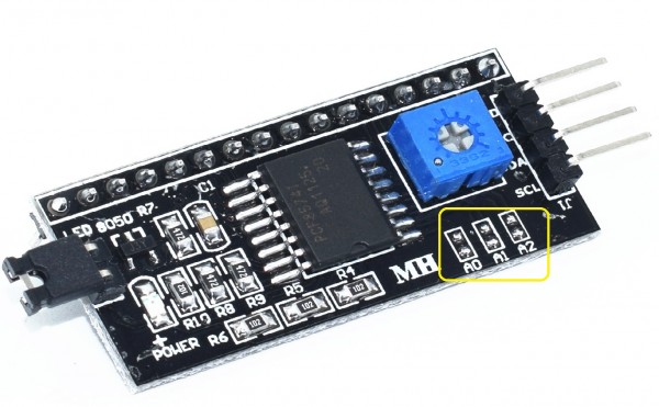
The better option, I think, would be to use one of those cheap 16x2 LCD displays with I2C interface sub-board. This way you need only 2 pins from Nano (SCL and SDA) plus supply line. They are on A4 and A5 so maybe you should consider rearranging your input/output pins. LCD display is much more versatile, you can use it also for system/MIDI debugging.
Personally I am using Arduino Mega Mini Pro Embedded (with USB) boards having a lot of pins but there is always too little input/output pins as multiplexing inputs in not an option for me (performance) when one board controls also many other things in real time. |
|
|
Back to top
|
|
|
PHOBoS
Joined: Jan 14, 2010
Posts: 5881
Location: Moon Base
Audio files: 709
|
| Posted: Mon Jul 09, 2018 6:36 am Post subject:
|
|
|
I did consider an LCD and it would definitely be more versatile. But because I am not planning to add other functions
besides just parameter controls it would be a bit overkill. I also opted for a LED display as it fits better with the looks
of the synth which has them as well. I'll use shiftregisters so it will only need 3 arduino pins.
I am also experimenting a bit with an arduino based sequencer which probably will get an LCD. I haven't looked into
I2C ones yet but that's good suggestion to save me some pins.
_________________
"My perf, it's full of holes!"
http://phobos.000space.com/
SoundCloud BandCamp MixCloud Stickney Synthyards Captain Collider Twitch YouTube |
|
|
Back to top
|
|
|
PHOBoS
Joined: Jan 14, 2010
Posts: 5881
Location: Moon Base
Audio files: 709
|
| Posted: Mon Jul 09, 2018 2:31 pm Post subject:
|
|
|
I worked a bit more on the button callibration code but I noticed some variations in the readings depending on how firmly I press the buttons.
I don't know if it is just contact bounce and haven't noticed any problems yet while testing the controller. I could add some buffers to the
switches to get more reliable readings, in which case I could also use an R2R, but now that I know I can use the analog pins I'll go back to what
I started with; switches connected directly to arduino pins.
I don't think there is a lot more I can do at the moment code wise untill I actually built the hardware, or at least untill I have the displays. I did
order all the parts I think I'll be needing and in the meantime I can start on the frontpanel design.
_________________
"My perf, it's full of holes!"
http://phobos.000space.com/
SoundCloud BandCamp MixCloud Stickney Synthyards Captain Collider Twitch YouTube |
|
|
Back to top
|
|
|
ixtern
Joined: Jun 25, 2018
Posts: 145
Location: Poland
|
| Posted: Tue Jul 10, 2018 4:24 am Post subject:
|
|
|
| PHOBoS wrote: | I worked a bit more on the button callibration code but I noticed some variations in the readings depending on how firmly I press the buttons.
I don't know if it is just contact bounce and haven't noticed any problems yet while testing the controller. I could add some buffers to the
switches to get more reliable readings, in which case I could also use an R2R, but now that I know I can use the analog pins I'll go back to what
I started with; switches connected directly to arduino pins.
I don't think there is a lot more I can do at the moment code wise untill I actually built the hardware, or at least untill I have the displays. I did
order all the parts I think I'll be needing and in the meantime I can start on the frontpanel design. |
I've also have a problem with Arduino and contact bouncing. There is an excellent page about hardware and software debouncing:
http://www.ganssle.com/debouncing-pt2.htm .
I am always going hard way so planning to use 74C922 key encoders with buit-in hardware debouncing - also to save some input pins I am always short of (old chips but got quite cheap from China).
Regarding I2C LCD: it's really easy to use with Arduino (using dedicated libraries). Small example:
| Code: |
#include <LiquidCrystal_I2C>
...
// LCD address: 0x3F
// syntax: LiquidCrystal_I2C(lcd_Addr,En,Rw,Rs,d4,d5,d6,d7,backlighPin,pol = POSITIVE)
LiquidCrystal_I2C lcd(0x3F, 2, 1, 0, 4, 5, 6, 7, 3, POSITIVE);
char bufferNoteOn[20] = "";
lcd.begin(20,4); // initialize the LCD for a 20 chars and 4 line display
lcd.backlight();
lcd.clear();
...
sprintf(bufferNoteOn, "NoteOn: %03d-%03d-%03d ", channel, midi_note_no, velocity);
row = 2;
col = 0;
lcd.setCursor(col,row);
lcd.print(bufferNoteOn);
... |
Not very complicated, isn't it? |
|
|
Back to top
|
|
|
PHOBoS
Joined: Jan 14, 2010
Posts: 5881
Location: Moon Base
Audio files: 709
|
| Posted: Tue Jul 10, 2018 11:40 am Post subject:
|
|
|
Thanks for the links with the debouncing info, it has some nice solutions. I prefer hardware debounce so you don't have to mess
around to get it working in code but at the same time it feels rather silly as a microprocessor is quite capable of handling it.
Also good to know the 74C922 has debounce built in. I have a couple of those chips but never experimented with them so
they might come in handy someday for debouncing.
As for the I2C LCD I didn't know yet there was a seperate library for it so I will look into that if I ever get one. I still have a couple
of 'regular' LCD's although most don't have a backlight. Since they are rather cheap these days I might as well get some new ones
with backlight and I2C control.
hmm, was just checking on ebay for some prices and there are I2C converter boards available, those could be useful for the
displays I already have. It also answers another thing I was wondering about; do they have a range of address settings ?
I have some I2C DACs and I can only select between 2 diffrent addresses so without any additional hardware I could only use 2
of those. The converter boards seem to have a range of 0X20~0X27 so no problems when I want to use it in combination with
the DACs.
_________________
"My perf, it's full of holes!"
http://phobos.000space.com/
SoundCloud BandCamp MixCloud Stickney Synthyards Captain Collider Twitch YouTube |
|
|
Back to top
|
|
|
ixtern
Joined: Jun 25, 2018
Posts: 145
Location: Poland
|
|
|
Back to top
|
|
|
PHOBoS
Joined: Jan 14, 2010
Posts: 5881
Location: Moon Base
Audio files: 709
|
|
|
Back to top
|
|
|
PHOBoS
Joined: Jan 14, 2010
Posts: 5881
Location: Moon Base
Audio files: 709
|
|
|
Back to top
|
|
|
PHOBoS
Joined: Jan 14, 2010
Posts: 5881
Location: Moon Base
Audio files: 709
|
|
|
Back to top
|
|
|
PHOBoS
Joined: Jan 14, 2010
Posts: 5881
Location: Moon Base
Audio files: 709
|
|
|
Back to top
|
|
|
ixtern
Joined: Jun 25, 2018
Posts: 145
Location: Poland
|
| Posted: Thu Aug 02, 2018 2:37 am Post subject:
|
|
|
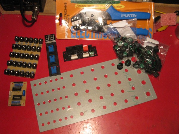
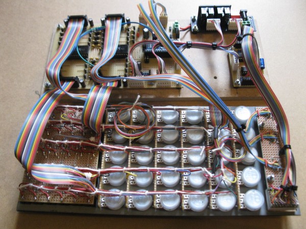
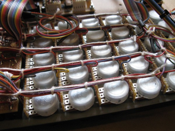
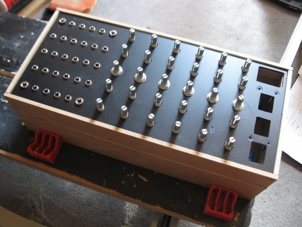
| PHOBoS wrote: | I did some more soldering and started on the frontpanel,
the knobs arrived today and I got myself a crimping tool. |
Controls packed little too dense for me but looks quite impressive. |
|
|
Back to top
|
|
|
PHOBoS
Joined: Jan 14, 2010
Posts: 5881
Location: Moon Base
Audio files: 709
|
| Posted: Sun Aug 19, 2018 6:31 am Post subject:
|
|
|

| Description: |
|
| Filesize: |
231.53 KB |
| Viewed: |
456 Time(s) |
| This image has been reduced to fit the page. Click on it to enlarge. |
|
| Description: |
|
| Filesize: |
234.03 KB |
| Viewed: |
440 Time(s) |
| This image has been reduced to fit the page. Click on it to enlarge. |
|
| Description: |
|
| Filesize: |
252.76 KB |
| Viewed: |
466 Time(s) |
| This image has been reduced to fit the page. Click on it to enlarge. |
|
_________________
"My perf, it's full of holes!"
http://phobos.000space.com/
SoundCloud BandCamp MixCloud Stickney Synthyards Captain Collider Twitch YouTube |
|
|
Back to top
|
|
|
gabbagabi

Joined: Nov 29, 2008
Posts: 652
Location: Berlin by n8
Audio files: 23
|
| Posted: Sun Aug 19, 2018 6:44 am Post subject:
|
|
|
 |
|
|
Back to top
|
|
|
PHOBoS
Joined: Jan 14, 2010
Posts: 5881
Location: Moon Base
Audio files: 709
|
|
|
Back to top
|
|
|
|

 Forum index » DIY Hardware and Software » Arduino