| Author |
Message |
jbeuckm

Joined: Nov 30, 2008
Posts: 165
Location: Stockholm
Audio files: 9
|
 Posted: Sun May 08, 2016 1:52 pm Post subject: Posted: Sun May 08, 2016 1:52 pm Post subject:
|
  |
|
| That sounds good for accents. What about triggers? Also, do you have any experience with multi-channel sample & hold ICs? eg. SMP08FPZ |
|
|
Back to top
|
|
 |
elmegil

Joined: Mar 20, 2012
Posts: 2179
Location: Chicago
Audio files: 16
|
| Posted: Sun May 08, 2016 6:17 pm Post subject:
|
|
|
I apologize, I suck at keeping context on threads that spread out over time.
Hm.....
The real 808 has a master clock that actually has the variable high trigger signal combined with it. Any given voice is enabled by its individual gate, but the trigger (going into the "Accent" part of the circuit as they are often labelled when made separate) is what made it actually sound. The microprocessor on the 808 runs on 5V, so that gate has to be a 5V gate, and could be driven directly by whatever MCU you plan to use.
This doesn't let you have separate accent per voice, but I'm sure part of why they did it this way is related to the same problem you're running up against.
May not help with your MIDI part of the project, but just some thoughts.... |
|
|
Back to top
|
|
|
jbeuckm
Joined: Nov 30, 2008
Posts: 165
Location: Stockholm
Audio files: 9
|
| Posted: Sun May 08, 2016 6:38 pm Post subject:
|
|
|
| I think you are saying that the signal through 22K to the first NPN's base on each voice is a 5V gate. In that case, I just keep that line at 5V and operate the voice with the "accent" 4-14V pulse, correct? |
|
|
Back to top
|
|
|
elmegil
Joined: Mar 20, 2012
Posts: 2179
Location: Chicago
Audio files: 16
|
| Posted: Sun May 08, 2016 7:39 pm Post subject:
|
|
|
If you leave it always on, then you're still going to have to solve the problem of triggering voices individually. Whereas if you do like the original does, and only gate the voices you want to sound on a given step, that can be handled by the MCU directly or with minimal buffering, and leave you to only need one set of circuitry to generate the 4 - 14V pulse.
If I'm not making any sense, I would recommend reading through the 808 service manual, it's actually pretty well described there. |
|
|
Back to top
|
|
|
jbeuckm
Joined: Nov 30, 2008
Posts: 165
Location: Stockholm
Audio files: 9
|
| Posted: Sun May 08, 2016 8:26 pm Post subject:
|
|
|
| In this MIDI version, there is no concept of steps and I am always triggering voices individually. Our 12 channel DAC or set of sample and hold circuits solve the problem of individual triggers, correct? So I could keep all gates at 5V and just send 12 separate scaled pulses for the instruments that should play. |
|
|
Back to top
|
|
|
elmegil
Joined: Mar 20, 2012
Posts: 2179
Location: Chicago
Audio files: 16
|
| Posted: Sun May 08, 2016 10:06 pm Post subject:
|
|
|
It's worth trying  |
|
|
Back to top
|
|
|
jbeuckm
Joined: Nov 30, 2008
Posts: 165
Location: Stockholm
Audio files: 9
|
| Posted: Mon May 09, 2016 7:37 am Post subject:
|
|
|
I guess the only signal that matters for separated voices is what happens at the collector of the PNP. I wish I thought of that before I built every single voice board with the gate circuit. Oh well  |
|
|
Back to top
|
|
|
jbeuckm
Joined: Nov 30, 2008
Posts: 165
Location: Stockholm
Audio files: 9
|
|
|
Back to top
|
|
|
jbeuckm
Joined: Nov 30, 2008
Posts: 165
Location: Stockholm
Audio files: 9
|
|
|
Back to top
|
|
|
RyBowk
Joined: Nov 25, 2018
Posts: 33
Location: England
|
| Posted: Thu Jan 10, 2019 5:09 am Post subject:
|
|
|
Hi, this is an amazing project, and the fact that you have made your hard work available to the public is just pure class!
I’m new to all of the synth building but I do love it and I’m learning every day.
Can I just ask a simple question? So the 6 pads x 2 that are on the midi - cv board, do they connect to the power distribution board to supply each module with cv and gate?
Sorry but I need to ask the silly questions to move forward 😊 many thanks Ryan |
|
|
Back to top
|
|
|
kropo
Joined: Jan 29, 2019
Posts: 16
Location: Finland
|
| Posted: Mon Mar 11, 2019 11:56 pm Post subject:
|
|
|
Hi
Wow this is nice looking project! Downloaded your all 808 files and midi cv drums, does this need something else to be build?
Regards
Jake |
|
|
Back to top
|
|
|
RyBowk
Joined: Nov 25, 2018
Posts: 33
Location: England
|
| Posted: Tue Mar 12, 2019 12:04 am Post subject:
|
|
|
| You will need a +/15v power supply. And a computer with midi |
|
|
Back to top
|
|
|
kropo
Joined: Jan 29, 2019
Posts: 16
Location: Finland
|
| Posted: Tue Mar 12, 2019 2:42 am Post subject:
|
|
|
Hi
Could be done only with 808 modules without midimodule if add 3.5mm connector to trigger and add potentiometer to acc? So that I could trigger these from sequencer without midi.
Regards
Jake
Last edited by kropo on Wed Mar 13, 2019 6:01 am; edited 1 time in total |
|
|
Back to top
|
|
|
RyBowk
Joined: Nov 25, 2018
Posts: 33
Location: England
|
| Posted: Tue Mar 12, 2019 3:25 am Post subject:
|
|
|
| Definitely, probably just a quick modification in eagle |
|
|
Back to top
|
|
|
kropo
Joined: Jan 29, 2019
Posts: 16
Location: Finland
|
| Posted: Wed Mar 13, 2019 12:31 am Post subject:
|
|
|
Hi
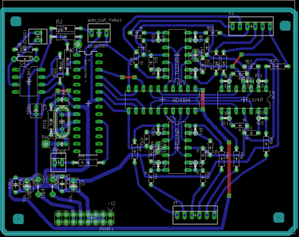
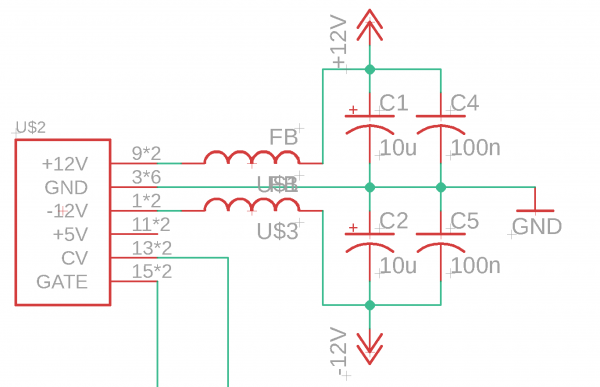
On a series of stupid questions, but what are these U$1,U$2, U$3 etc?
On BD U$2 is power connector, U$1 seems to be between +12V rail and U$3 between -12V rail, so are these output pins to somewhere or jumperwires?
Regards
Jake
Last edited by kropo on Wed Mar 13, 2019 6:01 am; edited 1 time in total |
|
|
Back to top
|
|
|
RyBowk
Joined: Nov 25, 2018
Posts: 33
Location: England
|
| Posted: Wed Mar 13, 2019 5:28 am Post subject:
|
|
|
| I don’t have the layout infront of me but at a guess I would say they are the trigger and accent outs, I will take a look when I’m home |
|
|
Back to top
|
|
|
kropo
Joined: Jan 29, 2019
Posts: 16
Location: Finland
|
|
|
Back to top
|
|
|
RyBowk
Joined: Nov 25, 2018
Posts: 33
Location: England
|
| Posted: Wed Mar 13, 2019 8:23 am Post subject:
|
|
|
| I’m pretty sure us2 is a generic name for the power connector |
|
|
Back to top
|
|
|
kropo
Joined: Jan 29, 2019
Posts: 16
Location: Finland
|
| Posted: Wed Mar 13, 2019 9:41 am Post subject:
|
|
|
Hi
Could be, but yet I don’t seem to understand where or what should be connected there. Power connector is giving -12v and 12v and after that these will break the connection.
Regards
Jake |
|
|
Back to top
|
|
|
RyBowk
Joined: Nov 25, 2018
Posts: 33
Location: England
|
| Posted: Wed Mar 13, 2019 10:34 am Post subject:
|
|
|
| Directly from +/-12v goes into a 100nanofarad capacitor that has a red line around it. Is that what you are referring to? |
|
|
Back to top
|
|
|
kropo
Joined: Jan 29, 2019
Posts: 16
Location: Finland
|
| Posted: Wed Mar 13, 2019 11:20 am Post subject:
|
|
|
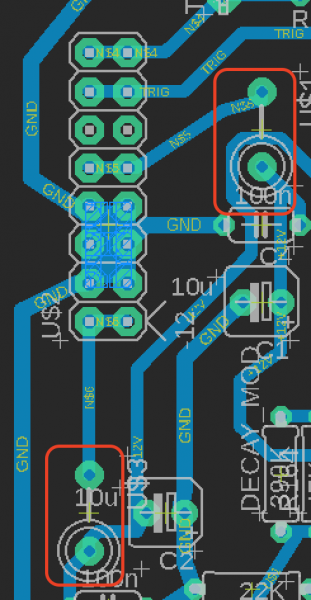
| RyBowk wrote: | | Directly from +/-12v goes into a 100nanofarad capacitor that has a red line around it. Is that what you are referring to? |
Hi
No, that’s C4 atleast in +12v side and its from ground.
Regards
Jake
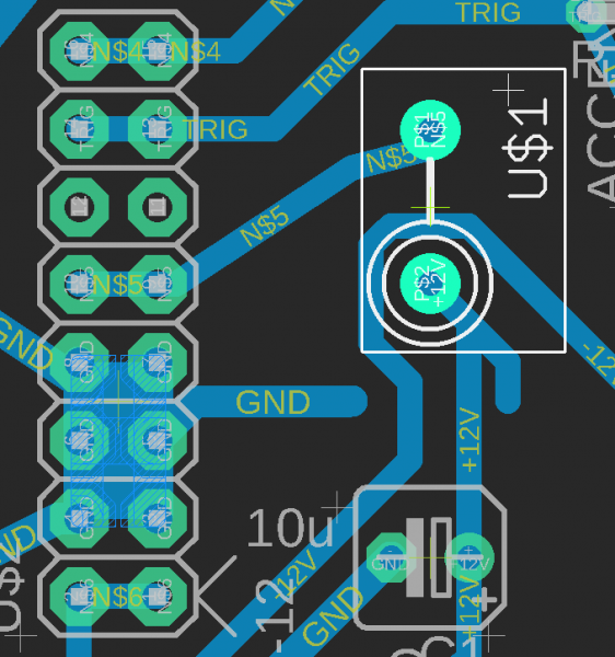
Edit. Picrure added. in the picture C4 is removed so it's much clearer image. So the U$1 here, I don't get it or what it should be.
Name: U$1
FootPrint: PB
Value: FB
Edit2, added picture from schematics.
| Description: |
|
| Filesize: |
175.6 KB |
| Viewed: |
278 Time(s) |
| This image has been reduced to fit the page. Click on it to enlarge. |
|
| Description: |
|
| Filesize: |
183.9 KB |
| Viewed: |
267 Time(s) |
| This image has been reduced to fit the page. Click on it to enlarge. |
|
|
|
|
Back to top
|
|
|
RyBowk
Joined: Nov 25, 2018
Posts: 33
Location: England
|
| Posted: Wed Mar 13, 2019 11:57 pm Post subject:
|
|
|
| Ahh I see what you mean, those are ferrite beads |
|
|
Back to top
|
|
|
kropo
Joined: Jan 29, 2019
Posts: 16
Location: Finland
|
| Posted: Thu Mar 14, 2019 12:03 am Post subject:
|
|
|
Hi
Thanks. Any idea what value or anything since the FB is not saying anything to me..
Regards
Jake |
|
|
Back to top
|
|
|
RyBowk
Joined: Nov 25, 2018
Posts: 33
Location: England
|
| Posted: Thu Mar 14, 2019 12:18 am Post subject:
|
|
|
| I’m at work at the moment but I’ll let you know what I used when I’m home |
|
|
Back to top
|
|
|
kropo
Joined: Jan 29, 2019
Posts: 16
Location: Finland
|
| Posted: Thu Mar 14, 2019 12:28 am Post subject:
|
|
|
Hi
Thanks so much!
Regards
Jake |
|
|
Back to top
|
|
|
|

 Forum index » DIY Hardware and Software » The layout factory