| Author |
Message |
cslammy
Joined: Apr 27, 2018
Posts: 206
Location: USA
Audio files: 1
|
 Posted: Tue Dec 10, 2019 7:59 am Post subject:
Using Arduino to "linearize" a vactrol Posted: Tue Dec 10, 2019 7:59 am Post subject:
Using Arduino to "linearize" a vactrol
Subject description: This can be done I figure, has anyone done this already? |
  |
|
I have been working on a lag circuit and would like to make it voltage controlled, for the lag. I could use OTA I guess (I have seen that before) but wanted to see if I could use a vatrol or other opto.
The problem of course is that no 2 vactrols are alike, and the thing is crazy non musical for this sort of application.
OK let's tame that beast using our best, brightest buddies from Arduino and atmel?
Idea one:
I figure an arduino and lookup table could be used to force the vactrol to behave in whatever way we want.
I also think you'd just use PWM out to "light up" the vactrol's LED so it's a low parts count circuit fragment--buffer the CV input and then hook the PWM to a resistor then to the LED anode of the vactrol.
With that in hand you can control all sorts of things in a more musical way....make it more linear, make it more log--yes, not good for v octave, but also not the odd non linear stuff we get forced into using out of an untamed vactrol.
use a lookup table?
for 100 ohms, use PWM frequency x.
For 150 ohms, use x1
for 250 ohms, use freq x2
for 1K ohms, use freq. x10
for 10K ohms, use freq x15
etc.
have the incoming CV sweep through this lookup table.
No, this still won't be super accurate, will probably be slow (Vactrols are slow by nature right) and I figure the lookup table will change based on the vactrol.
But it can be done, esp for things like portamento, attenunators, filters, etc.
Idea two:
Automate the lookup table creation!
Write some code that allows one arduino to blast these values into another arduino's lookup table.
So have a ohmmeter on arduino 2, sweep a vactrol with arduino one, then create the lookup table values based on what arduino #2 sees at the ohmmeter
Copy that output into the arduino's memory, and use Arduino 2 (attiny85 I figure? not sure it has enough ram, but something small. Pro mini?) to control the vactrol?
Has anyone already done either of these? I figure idea one should be pretty easy. But I don't think I've seen it before, which maybe means I am missing something obvious here.
Anyone (Grumble? Phobos?) want to weigh in and tell me I'm crazy? Unless I can be dissuaded I will experiment with idea 1. Idea 2 is a bit more out there but I figure it can be done.
Why not dudes?
_________________
Visit my AUDIODIWHY blog and website |
|
|
Back to top
|
|
 |
Grumble

Joined: Nov 23, 2015
Posts: 1319
Location: Netherlands
Audio files: 30
|
| Posted: Tue Dec 10, 2019 8:44 am Post subject:
|
|
|
First of all: I have never worked with vactrols, but I do know they are relatively slow.
If you wish to control the brightness of an LED you use PWM (Pulse Width Modulation), something I have never done as well  but I can see two problems: but I can see two problems:
1 - From what I read, the frequency used for controlling LED brightness is around 50Hz, and I'm afraid that even the slow vactrol will follow that frequency in some degree and in that case it will be audible.
2 - The usual bit-depth is 8 bits, so 256 degrees of brightness, is that enough?
Why not use a digital controllable potentiometer, if you still wish to use an Arduino?
They come even with 1024 steps...
_________________
my synth |
|
|
Back to top
|
|
|
cslammy
Joined: Apr 27, 2018
Posts: 206
Location: USA
Audio files: 1
|
| Posted: Tue Dec 10, 2019 8:54 am Post subject:
|
|
|
| Grumble wrote: | First of all: I have never worked with vactrols, but I do know they are relatively slow.
1 - From what I read, the frequency used for controlling LED brightness is around 50Hz, and I'm afraid that even the slow vactrol will follow that frequency in some degree and in that case it will be audible.
|
I could always use a I2C D to A...but trying to do this with minimal parts. That's one of the goals.
You can also an RC low pass to smooth the PWM right?
| Grumble wrote: |
2 - The usual bit-depth is 8 bits, so 256 degrees of brightness, is that enough?
|
Yes, this would not be used for things that need a high degree of resolution--but was also thinking a limit to the size of lookup table is in order as well.
I didn't want to contend with too many values.
For some apps that's fine, but I thought there were severe limits to the amount of current that can be pushed through most of those? (I have little experience with digital pots....)
And a vactrol doesn't have that sensitive a limit?
Also, general Q: do digital pots come in 1M or 2M values? Vactrols can go to very high resistance. The lag circuit needs at least 1M, although I guess I could greatly increase its cap size. But I am thinking generally about this....
But I do respect the suggestion of using digital pots when it makes sense. Thanks Grumble. 
_________________
Visit my AUDIODIWHY blog and website |
|
|
Back to top
|
|
|
Grumble
Joined: Nov 23, 2015
Posts: 1319
Location: Netherlands
Audio files: 30
|
|
|
Back to top
|
|
|
cslammy
Joined: Apr 27, 2018
Posts: 206
Location: USA
Audio files: 1
|
| Posted: Tue Dec 10, 2019 4:41 pm Post subject:
|
|
|
| Quote: | the Pmax is around 175mW for the used LDR,
|
175mW--I am using max 5V DC, that's 35mA max?
That's pretty good for what I'm trying to do.
For AD pots, AN1121 document, I see this:
"in all cases, the maximum current typically does not exceed a few milliamperes. "
From:
https://www.analog.com/media/en/technical-documentation/application-notes/AN-1121.pdf?doc=an-1291.pdf
Data sheet checks needed, but since the vactrol on average can tolerate more current, I'm pretty sure, and can go up to several megaohms resistance, I am going to mess with this, yes, not sure how useful it will be....
I also have some digital pots somewhere in the junk box to compare....
Thanks.
_________________
Visit my AUDIODIWHY blog and website |
|
|
Back to top
|
|
|
Grumble
Joined: Nov 23, 2015
Posts: 1319
Location: Netherlands
Audio files: 30
|
| Posted: Wed Dec 11, 2019 12:11 am Post subject:
|
|
|
| Quote: | | 175mW--I am using max 5V DC, that's 35mA max? |
Depends...
Using 5 volt and needing 35mA the maximum resistance of the LDR in the vactrol is a little over 142 ohms, as soon as the resistance goes over 142 mA you will not get 35mA.
So, now you have an arduino, R/C network for PWM DC to Dc converter, an opamp to act as a buffer for this voltage and a vactrol, but only 256 steps for your lookup table (which can be extended to 16 bit, read THIS)
_________________
my synth |
|
|
Back to top
|
|
|
cslammy
Joined: Apr 27, 2018
Posts: 206
Location: USA
Audio files: 1
|
| Posted: Wed Dec 11, 2019 8:03 am Post subject:
|
|
|
[quote="Grumble"] | Quote: | | only 256 steps for your lookup table (which can be extended to 16 bit, read THIS) |
didn't know abut that library, thanks. Great link!
Overall, I think optos in audio design is like painting with a blunt tipped airbrush--Good for some things, but you don't want to use it for everything.
I'll mess around with arduino/opto on the bench and see if I can come up with anything useful. Hours of fun ahead!
_________________
Visit my AUDIODIWHY blog and website |
|
|
Back to top
|
|
|
Grumble
Joined: Nov 23, 2015
Posts: 1319
Location: Netherlands
Audio files: 30
|
| Posted: Wed Dec 11, 2019 9:50 am Post subject:
|
|
|
| Quote: | | .Hours of fun ahead! |
That’s the spirit 
_________________
my synth |
|
|
Back to top
|
|
|
MapacheRaper

Joined: Feb 15, 2018
Posts: 166
Location: Spain
|
| Posted: Fri Dec 13, 2019 11:47 am Post subject:
|
|
|
I like the idea: an arduino app that "scans" the vactrol, writes a table of results and then tries to linearize log or expo the result. As Im imagining it it will have a lot of developing work but I dont see why it shouldnt work (with the natural inconsistencies and ilinearities of the vactrols), but It should work.
And it that works I can imagine a lot of people using the library after.
If I where going to do so I would try to do the PWM in the Khz or Mhz, not at 50Hz. Also, a RC filter is just 2 components or 4 if you want to do second order.
Anyway, cool idea. I hope we see the results in a future post on audiowhy |
|
|
Back to top
|
|
|
cslammy
Joined: Apr 27, 2018
Posts: 206
Location: USA
Audio files: 1
|
|
|
Back to top
|
|
|
MapacheRaper
Joined: Feb 15, 2018
Posts: 166
Location: Spain
|
| Posted: Sun Dec 15, 2019 4:46 pm Post subject:
|
|
|
Delicious post, Mr Lamm. I enjoy inmensely every new pots.
In fact I have an esp8266 looking at me. I know I have pretty much exploit the venerable atmega 328p till the limit and the ESP is the next one in been explored and tinkered... 
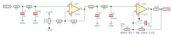
Regarding the PWM filtering (for the nano at least) Kassutronics has a pretty much perfect filter in this design:
https://github.com/kassu/KassutronicsQuantizer
The filtering is so good that you can perfectly quantize CVs for the modular with it and only takes 4 resistors and 4 caps. In fact I use just half of the poles it and keeps working wonders |
|
|
Back to top
|
|
|
MapacheRaper
Joined: Feb 15, 2018
Posts: 166
Location: Spain
|
|
|
Back to top
|
|
|
PHOBoS

Joined: Jan 14, 2010
Posts: 5873
Location: Moon Base
Audio files: 709
|
|
|
Back to top
|
|
|
cslammy
Joined: Apr 27, 2018
Posts: 206
Location: USA
Audio files: 1
|
| Posted: Mon Dec 16, 2019 8:21 am Post subject:
|
|
|
| MapacheRaper wrote: | | The filter . I just use r2, r3, c5, c1, but you can make it double to even clean more the pwm signal |
Thanks Mapache for this. I can see a lot of uses for this filter.
I'll keep working on this and post again.
_________________
Visit my AUDIODIWHY blog and website |
|
|
Back to top
|
|
|
Electric Druid

Joined: Mar 13, 2012
Posts: 44
Location: UK
|
| Posted: Thu Dec 19, 2019 4:52 pm Post subject:
|
|
|
If you're using the PWM to drive a Vactrol's LED, you don't need any filtering. In fact, you're definitely better off without it. You said in your blog post "could it be that easy?" - the answer's "Yes!" and that's one of the best reasons for doing it! The LED's response is more linear given a PWM input than a variable-voltage input (which is what you get if you filter it. So don't filter!
Example of a multimode filter like yours, driven by a PWM signal..ok, actually it's PDM in this case, but it's a very similar thing:
https://electricdruid.net/filterfx-lp-bp-hp-lfo-filter/
Just run the PWM direct (one series resistor) to the LED. Then you need some way to feed the LDR response back to the uP for measurement. Once you've got that you can determine the vactrols' response.
The classic way would be like the 1980's synth tuning routines: You're trying to achieve a given value X (in this case an LDR resistance) so you set the highest bit of your output. If the LDR's response is too low, you leave it set and move onto the next bit down. If it's too high, you unset it and move onto the next bit down. When you get to the bottom of however many bits you have, you've got a digital value that produces as close to the value you wanted as you can get.
You could also generate a table of log or expo values in the same way. Have an LDR value you're aiming at, and then reach the required PWM output value by successive approximation. In fact, why stop there? - you could do "s" curves too and whatever else you can dream up. The problem on old synths was that doing this for bass notes was pretty slow, and that could potentially be an issue here if the LDRs reposes is very slow. It is on some vactrols, and light-to-dark is different from dark-to-light, so there might be a better direction to run the tests, either bottom to top or top to bottom.
Finally, 8 bits might be the typical PWM resolution on an Arduino (I dunno - not my thing), but the underlying processors can often do 10-bit or even 12-bit without any difficulty, and at many-KHz speeds. I use PICs with 10-bit PWM output at 39KHz.
_________________
Electric Druid Synth and Pedal DIY website |
|
|
Back to top
|
|
|
cslammy
Joined: Apr 27, 2018
Posts: 206
Location: USA
Audio files: 1
|
| Posted: Thu Dec 19, 2019 5:11 pm Post subject:
|
|
|
Thanks.
I just got my first 2 ESP32 dev boards which do 15 bit PWM out of the box. probably more than I need. Also 8 bit D to A x2 on the board. They were really easy to get working on a Fedora Linux/Arduino IDE setup.
I will continue to experiment with this and post.
But, I have been thinking about this a lot. it would be nice to do some sort of feedback to read the resistance of the Vac as it does its thing, but that could get pretty complicated fast.
I was thinking to do that accurately I'd need to read voltage drop across the resistor part of vac (easy if you buffer it), so that's the V in ohms law, but also the current (which means adding some sort of shunt setup) to calculate the VAC behavior "on the fly". The current measurement would need more buffering so now I think you're looking at a TL074.
With V and i it's easy to get at what the vac is really doing using ohms law.
then goose up or down the PWM using the ESP32 to get the incoming CV to do what you really want it to do.
And of course we are often dealing with AC flowing through the resistor side of the vac, ok now what? RMS conversion of V?
So I don't know how much trouble to go to here. I guess that's always the question? Anyone want to weigh in have at it. How much work is it worth to have a VAC behave a bit more like a digital pot? Maybe not that much?
_________________
Visit my AUDIODIWHY blog and website |
|
|
Back to top
|
|
|
MapacheRaper
Joined: Feb 15, 2018
Posts: 166
Location: Spain
|
| Posted: Thu Dec 19, 2019 8:31 pm Post subject:
|
|
|
Doubth sees the obstacles, faith sees the way.
Go for it or you couldnt sleep in peace and will have vactrol nightmares!
Electricdruid... They call him electricdruid for something... Vactrols doesnt need PWM filtering... so true! What we were thinking about?!?!?
|
|
|
Back to top
|
|
|
Grumble
Joined: Nov 23, 2015
Posts: 1319
Location: Netherlands
Audio files: 30
|
| Posted: Fri Dec 20, 2019 3:12 am Post subject:
|
|
|
| Quote: | | Vactrols doesnt need PWM filtering... |
| Quote: | | The LED's response is more linear given a PWM input than a variable-voltage input (which is what you get if you filter it. So don't filter! |
About the linearity when PWM modulating an LED: Sure!
My remark about filtering was because a lot of pwm led control uses 50Hz as base frequency, and I'm (almost) sure that 50Hz will give a severe hum at the LDR side of the vactrol.
_________________
my synth |
|
|
Back to top
|
|
|
Electric Druid
Joined: Mar 13, 2012
Posts: 44
Location: UK
|
| Posted: Fri Dec 20, 2019 4:52 am Post subject:
|
|
|
| Grumble wrote: |
My remark about filtering was because a lot of pwm led control uses 50Hz as base frequency, and I'm (almost) sure that 50Hz will give a severe hum at the LDR side of the vactrol. |
Depends how slow the LDR is. But since the chip can produce a PWM output that is much faster than 50Hz, use a much faster speed. You should be able to do a good PWM output at 10s of KHz.
| Quote: | | it would be nice to do some sort of feedback to read the resistance of the Vac as it does its thing, but that could get pretty complicated fast. |
"essential" rather than "would be nice", I'd say. If you're going to get the thing to calibrate itself, it needs to be able to measure the output. Otherwise it's just guesswork.
| Quote: | | I was thinking to do that accurately I'd need to read voltage drop across the resistor part of vac (easy if you buffer it), so that's the V in ohms law, but also the current (which means adding some sort of shunt setup) to calculate the VAC behavior "on the fly". The current measurement would need more buffering so now I think you're looking at a TL074. |
While I can see that if you can measure V and I across the LDR, you can use Ohm's law to work out the resistance, this seems over-complicated.
If the LDR is half of a voltage-divider, the voltage alone is enough. We 've got the standard voltage divider equation:
Vout = Vin * R2 / (R1+R2)
We can rearrange it to give us R2:
R2 = (Vout * R1) / (Vin-Vout)
(This is shown here: https://electronics.stackexchange.com/questions/150771/how-can-i-rearrange-the-voltage-divider-formula-for-r2 )
We know already what voltage we have at the top of the divider (say 5V), and we know the fixed value of R1, so we only need to measure the Vout by feeding it to an ADC input on our chip. Finding the current is unnecessary.
(I've demonstrated this using the LDR as the bottom of the divider, but you could equally well do it using the LDR as the top and then rearrange to get R1).
_________________
Electric Druid Synth and Pedal DIY website |
|
|
Back to top
|
|
|
cslammy
Joined: Apr 27, 2018
Posts: 206
Location: USA
Audio files: 1
|
| Posted: Fri Dec 20, 2019 7:20 am Post subject:
|
|
|
| Electric Druid wrote: |
We know already what voltage we have at the top of the divider (say 5V), and we know the fixed value of R1, so we only need to measure the Vout by feeding it to an ADC input on our chip. Finding the current is unnecessary.
|
Thanks Druid. yes I was overthinking this. I do that sometimes.
I am also going to treat all V as DC passing through the vac as well at least for initial screwing around stages.
Electronics are like relationships--you have to set boundaries. 
_________________
Visit my AUDIODIWHY blog and website |
|
|
Back to top
|
|
|
cslammy
Joined: Apr 27, 2018
Posts: 206
Location: USA
Audio files: 1
|
| Posted: Fri Dec 20, 2019 7:31 am Post subject:
|
|
|
| MapacheRaper wrote: |
Go for it or you couldnt sleep in peace and will have vactrol nightmares!
|
So so SOOO true! I don't know what keeps me up more, thinking about mpus and vacs or nightmares about Mapache Pete Townshending the hell out of their martins and replacing 'em with behringer MS20 clones. 
_________________
Visit my AUDIODIWHY blog and website |
|
|
Back to top
|
|
|
cslammy
Joined: Apr 27, 2018
Posts: 206
Location: USA
Audio files: 1
|
| Posted: Thu Dec 26, 2019 8:22 pm Post subject:
It was real, it was fun, but it wasn't real fun! |
|
|
https://audiodiwhy.blogspot.com/2019/12/vactrols-controlled-by-arduinos-part-ii.html
Spent a lot of time on this, got some interesting results but at the end of the day couldn't get this working reliably and couldn't get it to work at all on ESP32.

Whatever. In the midst of that I started to experiment with using Vinyl for front panel art which is working better than I thought. Onward.
_________________
Visit my AUDIODIWHY blog and website |
|
|
Back to top
|
|
|
MapacheRaper
Joined: Feb 15, 2018
Posts: 166
Location: Spain
|
| Posted: Sun Dec 29, 2019 3:54 am Post subject:
|
|
|
Even if 2-3 of these days on the workbench sucked, the article/post rocks. You found the workable range of the vacs to share with the community and write a script and possible ways to taking it further.
The esp chips are so powerful and cheap, but seems like bitches to program, isnt?. When I read about them I thought they were to produce next generation synth delicatessens, like an ornament and crimes interfaced with the smartphone, so you can use the screen to control things in the modular. However it seems noone is getting to the deep guts of the ESP, maybe because they are not well docummented?.
In any case ,a delicious post, Charlie. For a 2020 full of electronic joys and pleasures. Cheers |
|
|
Back to top
|
|
|
|

 Forum index » DIY Hardware and Software » Arduino