| Author |
Message |
e1999
Joined: Apr 25, 2019
Posts: 29
Location: naples
|
|
|
Back to top
|
|
 |
blue hell
Site Admin

Joined: Apr 03, 2004
Posts: 24506
Location: The Netherlands, Enschede
Audio files: 298
G2 patch files: 320
|
 Posted: Fri Jan 24, 2020 6:26 am Post subject: Posted: Fri Jan 24, 2020 6:26 am Post subject:
|
  |
|
You may want to rectify and filter your touch point. On toching you probably will introduce mains hum causing the switch to go on/off at the mains rate - which would then be displayed as an average value by a voltmeter set to DC.
Edit: this can be done after the buffering port. But what you should also do is add some protection diodes and a resistor on that port's input - as is you may blow the port when charged up to sparky level after walking on a dry carpet or something (see 2nd post in this thread for an example: http://electro-music.com/forum/topic-14912.html - the resistor could be much higher than 200 Ohms).
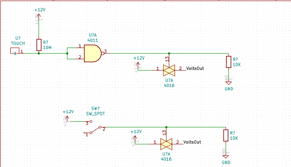
Re. the offset, you should add a pull down resistor on the output of the switch. This should be something in the order 100k ... must be large compared to the on-state resistance of the switch (which typically is 400 Ohms but worst case it can be 2k5 - this should at least better things up 
Edit: The reason for this is that the switch has a small leakage current, and when you have nothing connected to it's output (a voltmeter has a high impedance input - which would count as almost nothing connected) som voltage will develop.
_________________
Jan
also .. could someone please turn down the thermostat a bit.
 |
|
|
Back to top
|
|
|
JovianPyx

Joined: Nov 20, 2007
Posts: 1988
Location: West Red Spot, Jupiter
Audio files: 224
|
| Posted: Fri Jan 24, 2020 7:18 am Post subject:
|
|
|
Pull down resistor at the switch's output should fix the leakage problem.
Yes, there would be 50Hz introduced by the touch into the gate. I would filter after pin 3 of the gate because you want the touch input to remain at an extremely high input impedance. An RC filter made of 10K ohms and 0.47uF should have a cutoff of 33 Hz, this may take care of the noise. (I used this tool to calculate the filter's part values)
_________________
FPGA, dsPIC and Fatman Synth Stuff
Time flies like a banana.
Fruit flies when you're having fun.
BTW, Do these genes make my ass look fat?
corruptio optimi pessima
|
|
|
Back to top
|
|
|
PHOBoS

Joined: Jan 14, 2010
Posts: 5881
Location: Moon Base
Audio files: 709
|
| Posted: Fri Jan 24, 2020 10:30 am Post subject:
|
|
|
What exactly are you doing with the 12V, most importantly what is the maximum current ?
Also if you only want to switch a DC voltage of 12V and the circuit is powerd by 12V aswell there is a better solution: an AND gate.
edit: actually in that case you wouldn't even need a gate 
_________________
"My perf, it's full of holes!"
http://phobos.000space.com/
SoundCloud BandCamp MixCloud Stickney Synthyards Captain Collider Twitch YouTube
Last edited by PHOBoS on Fri Jan 24, 2020 2:20 pm; edited 1 time in total |
|
|
Back to top
|
|
|
Grumble

Joined: Nov 23, 2015
Posts: 1319
Location: Netherlands
Audio files: 30
|
| Posted: Fri Jan 24, 2020 1:23 pm Post subject:
|
|
|
Why do it the hard way?
Check THIS out!
A number of capacitive touch modules for sale at Aliexpress
_________________
my synth |
|
|
Back to top
|
|
|
PHOBoS
Joined: Jan 14, 2010
Posts: 5881
Location: Moon Base
Audio files: 709
|
| Posted: Fri Jan 24, 2020 2:10 pm Post subject:
|
|
|
Yes, for touch sensors those are very nice. When I intially got them I was under the impression they would have to be used with a microcontroller
but they're actually standalone circuits with a digital output. If I recall correctly the used chips also have a latching option but it might be tricky
to change that depending on the module.
_________________
"My perf, it's full of holes!"
http://phobos.000space.com/
SoundCloud BandCamp MixCloud Stickney Synthyards Captain Collider Twitch YouTube |
|
|
Back to top
|
|
|
e1999
Joined: Apr 25, 2019
Posts: 29
Location: naples
|
| Posted: Fri Jan 24, 2020 3:17 pm Post subject:
|
|
|
guys thanks for the response
@Blue Hell
thanks for the heads up on diode protection of the input, I will definitely put that into the circuit!
this may be a dumb question, but what exactly do you mean by rectifying the touch point?
I did try putting a gate buffer on the output of the 4011 made of an npn and pnp transistor which basically takes any positive voltage and makes it equal to the supply voltage, is something like that what you mean?
@Blue Hell and @JovianPyx
pull down resistor in fact solved the leakage.
re:filtering, I tried out various rc combinations and it seems that if either the cap or the resistor is too high a value the 4016 won't switch. the best combination I found was 1K with 1UF resulting in around 8.7v output, not bad but unfortunately not exactly what I was looking for either.
@Phobos
I want to use this for generating cv values. The idea at the moment is to make a 4017 based sequencer that can double as a touch programmer. This is why its important that it is able to pass through the supply voltage. So that the touch values correspond to the sequence values set by the shared knobs. I'm not sure what the maximum current is, but I'm under the assumption that if its being used to supply cv for example to an oscillator or a filter, it's not using very much. I know how to measure the circuit's total consumption with a multimeter but is there any way to measure only how much current the CV into for example a cutoff filter is using?
Re: AND gate, I think I see what you mean. I mean ideally this whole operation could be accomplished with only the 4011 and the two resistors, if it weren't for the fact that the touch point is actually turning the switch on and off. With an AND gate in place of the 4016, you would still have to somehow substantially smooth out the output of the NAND gate to be able to get the supply voltage coming through, no? Have to think on this some more...
@Grumble and @Phobos
yea believe me, I can totally understand why one would choose an easier more convenient route like those modules there. but I'm interested in more fundamental approaches for a number of reasons. a big part of it is being able to customize the form /materials/interface of the touch sensor, being able to make it out of common parts rather than having to buy specialty parts, also because its a subject I find particularly interesting and want to know more about.
Anyways I imagine at some point I'll buy some of those, even if just to try and see how they're doing it. But for now I'm going to see if I can persevere in this direction and figure out some kind of solution. |
|
|
Back to top
|
|
|
blue hell
Site Admin
Joined: Apr 03, 2004
Posts: 24506
Location: The Netherlands, Enschede
Audio files: 298
G2 patch files: 320
|
| Posted: Fri Jan 24, 2020 3:35 pm Post subject:
|
|
|
| e1999 wrote: |
this may be a dumb question, but what exactly do you mean by rectifying the touch point? |
A diode and a capacitor, and a resistor to discharge the capacitor - otherwise it would just hang after being charged once. This is actually the same circuit as used for a simple AM detector. For example see the schematic @ https://blog.digilentinc.com/pushing-the-envelope-detector-exploring-demodulation-am-and-fm-signals/ - the one with D1, R7 and C3 (2nd image on the page) - you may need to fiddle a bit with the value of C3 - it may want to be larger.
This will rectify the hum you put in trough your finger to a DC level. This circuit should be after the NAND port in your schematic.
Edit : the nand port would be your buffer - adding stuff on the left side (except for the input protection) would make it less sensitive indeed, but after it you can do a lot more for signal conditioning. An RC filter only would not do much except attenuate the signal a bit - the diode is really need for peak detection.
It may work better to to "invert" the am (peak) detector .. in that the C and R do not go to ground but to + 12V instead and the diode is being reversed - but I am not too sure about that. The thing is .. the capacitor will be charged faster trough the diode than it will be decharged trough the resistor, which mught result in a noticible difference in the time needed to switch on and the time needed to switch off - with the "reversal" you will reverse that timing.
Edit2: and erm .. only trough dumb questions can we learn anything .. so actually there is no such thing as a dumb question.
Edit3 - for the am / peak detection also have a look at https://electronics.stackexchange.com/questions/293633/what-role-does-the-capacitor-play-in-an-am-demodulating-circuit - it explains it better. In your case the RF signal is not really very RF but it is the mains hum, and you only have two AM levels, on and off.
Last edited by blue hell on Fri Jan 24, 2020 3:55 pm; edited 2 times in total |
|
|
Back to top
|
|
|
JovianPyx
Joined: Nov 20, 2007
Posts: 1988
Location: West Red Spot, Jupiter
Audio files: 224
|
| Posted: Fri Jan 24, 2020 3:44 pm Post subject:
|
|
|
That diode-cap-resistor circuit reminds me of a filter in a PSU. It's a filter that favors charging over discharging the cap. That could be the answer to the 8.7 volt problem as I suspect it's a DC volt meter reading and could actually be pulsating DC.
_________________
FPGA, dsPIC and Fatman Synth Stuff
Time flies like a banana.
Fruit flies when you're having fun.
BTW, Do these genes make my ass look fat?
corruptio optimi pessima
|
|
|
Back to top
|
|
|
PHOBoS
Joined: Jan 14, 2010
Posts: 5881
Location: Moon Base
Audio files: 709
|
| Posted: Fri Jan 24, 2020 5:03 pm Post subject:
|
|
|
OK, if you just want to use it to switch a voltage to create a CV with a potentiometer the current should be fine. I was wondering if you were planning
to use it to power other circuits, which could work but you'd have to keep an eye on the max current. Measuring the current can be tricky if it's not constant
otherwise you can just place an amp meter in series with the connection you want to measure. If you want to use both a 4017 and touch sensors to
select the same CV it will require some extra switching circuitry but I let you figure that out for now. I did do something similar with QuaZar though.
As for using an AND gate, let's see if I can clear it up. The 4016/4066 is a digitally controlled analog switch. Meaning you can use a digital signal to switch
a different analog (AC/DC) voltage. For example if you would create the CV with a potentiometer before switching it then that's what you would use.
An AND gate can be used as a digitally controlled digital switch. In this case your +12v is the equivalent of a digital high signal (since it is the same as the
supply voltage). So if you connect it to 1 input of the AND gate you can use the other input to switch it on/off. However, if it will always just be +12V
there is no need for a switch at all since the digital signal you use to control it already does what you want. You could use it to buffer the signal though but
then it doesn't necessarily have to be an AND gate. First thing you have to do is get a clean digital signal from your touch sensor which can be done with
the suggestions from Blue Hell and JovianPyx. It might need a comparator for the best results.
| Quote: | | yea believe me, I can totally understand why one would choose an easier more convenient route like those modules there. but I'm interested in more fundamental approaches for a number of reasons. ... |
I completely understand. Note that with those touch sensors you can just solder a wire to the sensorpad and connect that to anything you want, so you don't have
to use the module itself as the actual sensor. There are also some chips that can handle 4/8 (or more) inputs but I am not sure if those have seperate outputs.
If you make your own circuit you can probably adjust the sensitivity more to your liking though and it shouldn't be very hard to do. It's also possible to make your
own capacitive switch circuit (so just like those modules) which mostly eliminates the need to add protective cricuitry on the input.
_________________
"My perf, it's full of holes!"
http://phobos.000space.com/
SoundCloud BandCamp MixCloud Stickney Synthyards Captain Collider Twitch YouTube |
|
|
Back to top
|
|
|
e1999
Joined: Apr 25, 2019
Posts: 29
Location: naples
|
| Posted: Sat Jan 25, 2020 10:11 am Post subject:
|
|
|
guys, once again excellent info and ideas,
I was able to get this thing working only thanks to your help!
It seems that a cap value of 2.2-10uf works best, with varying effect between different cap values being noticed only in certain use cases. I hope to play around with it some more this weekend when I have time.
As you all surmised, the touch point was switching on and off and if I connected the output of the 4011 directly to a twin-t input you could hear the oscillations becoming less and less exaggerated as the cap size was increased. I wasn't able to get the signal coming out of the 4011 to not oscillate at all, but it must have reduced the peaks enough to where when it was applied to the 4016 switch, the switch stayed on. I imagine a comparator could be used to clean this up even more as Phobos suggested.
good weekend to everyone! |
|
|
Back to top
|
|
|
JovianPyx
Joined: Nov 20, 2007
Posts: 1988
Location: West Red Spot, Jupiter
Audio files: 224
|
| Posted: Sat Jan 25, 2020 11:51 am Post subject:
|
|
|
Try the diode filter that Blue Hell suggested. I think that will fix it.
_________________
FPGA, dsPIC and Fatman Synth Stuff
Time flies like a banana.
Fruit flies when you're having fun.
BTW, Do these genes make my ass look fat?
corruptio optimi pessima
|
|
|
Back to top
|
|
|
e1999
Joined: Apr 25, 2019
Posts: 29
Location: naples
|
| Posted: Sun Jan 26, 2020 10:43 am Post subject:
|
|
|
| yes in fact that worked! |
|
|
Back to top
|
|
|
blue hell
Site Admin
Joined: Apr 03, 2004
Posts: 24506
Location: The Netherlands, Enschede
Audio files: 298
G2 patch files: 320
|
| Posted: Sun Jan 26, 2020 11:01 am Post subject:
|
|
|

_________________
Jan
also .. could someone please turn down the thermostat a bit.
|
|
|
Back to top
|
|
|
|

 Forum index » DIY Hardware and Software