| Author |
Message |
synthmonger
Joined: Nov 16, 2006
Posts: 578
Location: flada
Audio files: 3
|
 Posted: Sat Apr 04, 2009 6:23 pm Post subject: Posted: Sat Apr 04, 2009 6:23 pm Post subject:
 CMOS triple resonant VCF CMOS triple resonant VCF
Subject description: audio/video demos and PCB now available |
  |
|
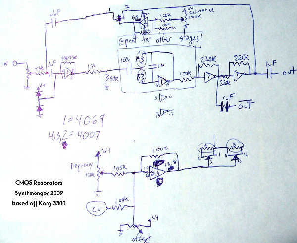
My design is loosely based on the Korg Resonators PS3100/3300. While they do share the same core filter design mine is very different. It is made using CMOS chips, has additional voltage control over resonance, inverted and non inverted outputs and can be overdriven for added distortion. It can self-oscillate as well.
The board is setup to run in euro-rack systems, of course it is not limited to this. It can operate on different voltages just fine. 9-18v all with pleasing results.
components used:
Four 4007
One 4069
37 resistors
19 caps
4 diodes
5 trim pots
You can find audio and visual documentation on my youtube, flickr and myspace pages. The pcb can be purchased on my etsy site.
http://www.myspace.com/synthmonger
http://www.youtube.com/synthmonger
http://synthmonger.etsy.com
http://www.flickr.com/photos/synthmonger/
_________________
Youtube!
modular demos!
Whacky tunes!
Last edited by synthmonger on Sun Jun 07, 2009 9:13 pm; edited 8 times in total |
|
|
Back to top
|
|
 |
Mikmo
Joined: Dec 01, 2005
Posts: 150
Location: Copenhagen - Denmark
|
| Posted: Sun Apr 05, 2009 12:48 am Post subject:
|
|
|
I like that sound. 
_________________
Stay Cool
Mikael
http://www.mikmo.dk |
|
|
Back to top
|
|
|
synthmonger
Joined: Nov 16, 2006
Posts: 578
Location: flada
Audio files: 3
|
| Posted: Sun Apr 05, 2009 2:04 am Post subject:
|
|
|
| Mikmo wrote: | | I like that sound. |
Thanks, but that doesn't qualify as a guess! |
|
|
Back to top
|
|
|
RF

Joined: Mar 23, 2007
Posts: 1502
Location: Northern Minnesota, USA
Audio files: 28
|
| Posted: Sun Apr 05, 2009 4:49 am Post subject:
|
|
|
I've not had all that much experience with different filters - but it sounds most like my CGS Steiner-Parker Synthacon.
_________________
www.sdiy.org/rfeng
"I want to make these sounds that go wooo-wooo-ah-woo-woo.”
(Herb Deutsch to Bob Moog ~1963) |
|
|
Back to top
|
|
|
slacker
Joined: Nov 18, 2007
Posts: 301
Location: England
Audio files: 11
G2 patch files: 1
|
| Posted: Sun Apr 05, 2009 6:04 am Post subject:
|
|
|
| That would be my guess, but only because I think you mentioned something about it in another thread. |
|
|
Back to top
|
|
|
synthmonger
Joined: Nov 16, 2006
Posts: 578
Location: flada
Audio files: 3
|
| Posted: Sun Apr 05, 2009 7:09 am Post subject:
|
|
|
| slacker wrote: | | That would be my guess, but only because I think you mentioned something about it in another thread. |
Nah it's not a CMOS synthacon. I didn't include it on the list because I just thought of it yesterday and thought "Oh I love this filter, I gotta cmos-o-fie it!"
Kinda sounds like 3 filters in parrallel... |
|
|
Back to top
|
|
|
v-un-v
Janitor


Joined: May 16, 2005
Posts: 8932
Location: Birmingham, England, UK
Audio files: 11
G2 patch files: 1
|
| Posted: Sun Apr 05, 2009 4:27 pm Post subject:
|
|
|
FYI, there was a vocoder design completely based on cmos chips published in ETI magazine back in the late 70's. I once had the magazine this design was in, but have since lost it. I'm curious to know if this design here would have been similar? Your circuit has a nice "phasey" sweep. 
_________________
ACHTUNG!
ALLES TURISTEN UND NONTEKNISCHEN LOOKENPEEPERS!
DAS KOMPUTERMASCHINE IST NICHT FÜR DER GEFINGERPOKEN UND MITTENGRABEN! ODERWISE IST EASY TO SCHNAPPEN DER SPRINGENWERK, BLOWENFUSEN UND POPPENCORKEN MIT SPITZENSPARKSEN.
IST NICHT FÜR GEWERKEN BEI DUMMKOPFEN. DER RUBBERNECKEN SIGHTSEEREN KEEPEN DAS COTTONPICKEN HÄNDER IN DAS POCKETS MUSS.
ZO RELAXEN UND WATSCHEN DER BLINKENLICHTEN. |
|
|
Back to top
|
|
|
synthmonger
Joined: Nov 16, 2006
Posts: 578
Location: flada
Audio files: 3
|
| Posted: Sun Apr 05, 2009 5:12 pm Post subject:
|
|
|
| v-un-v wrote: | | FYI, there was a vocoder design completely based on cmos chips published in ETI magazine back in the late 70's. I once had the magazine this design was in, but have since lost it. I'm curious to know if this design here would have been similar? Your circuit has a nice "phasey" sweep. |
Oh no way! I gotta find the ETI article. I'm very interested in building a CMOS vocoder.
But no it wasn't from that article. My design is based off the Korg 3100/3300 resonators. I swapped op-amps for 4069 gates as linear amps and vactrols for 4007s.
I need to breadboard the resonator using the original design and compare the two side by side. I've built one before and I don't think my cmos version has as much "oomff" as the Korg version. I used all the ins and outs so there are a few additions to mine, like inverted and non inverted outputs, drive control, and maybe a master cv resonance control.
Schematic this week! |
|
|
Back to top
|
|
|
synthmonger
Joined: Nov 16, 2006
Posts: 578
Location: flada
Audio files: 3
|
| Posted: Sun Apr 05, 2009 11:10 pm Post subject:
|
|
|
I got the extra "oomf" and worked out a pretty cool master resonance control. In the process of getting the VC resonance I found a VC distortion that gives a neat pulsey and syncy kinda sound.
Time to start working on the schematic and pcb!
Last edited by synthmonger on Mon Apr 06, 2009 8:01 am; edited 1 time in total |
|
|
Back to top
|
|
|
scriptstyle

Joined: Jan 22, 2008
Posts: 250
Location: nj
|
| Posted: Mon Apr 06, 2009 12:25 am Post subject:
|
|
|
| This is very cool can't wait to see the schematic! |
|
|
Back to top
|
|
|
synthmonger
Joined: Nov 16, 2006
Posts: 578
Location: flada
Audio files: 3
|
| Posted: Mon Apr 06, 2009 10:38 am Post subject:
|
|
|
| I found an ETI vocoder article from 1980 on CAG's site, though it only uses some CMOS chips not all. Is this the same one v-un-v? |
|
|
Back to top
|
|
|
synthmonger
Joined: Nov 16, 2006
Posts: 578
Location: flada
Audio files: 3
|
|
|
Back to top
|
|
|
synthmonger
Joined: Nov 16, 2006
Posts: 578
Location: flada
Audio files: 3
|
|
|
Back to top
|
|
|
loss1234

Joined: Jul 24, 2007
Posts: 1536
Location: nyc
Audio files: 41
|
|
|
Back to top
|
|
|
loss1234
Joined: Jul 24, 2007
Posts: 1536
Location: nyc
Audio files: 41
|
| Posted: Tue Apr 07, 2009 4:32 am Post subject:
|
|
|
also
on the chip (4007?) that is feeding the A and B fake vactrols, i notcied that pin numbers are 10/6, and 13/8 (And the chip is labeled 3/4)
so does this mean that vactrol A gets a circuit like this and Vactrol B gets one as well? or does it just mean, use whichever set of pins you like?
that is a bit vague
also on the top 4007 inverter (resonance) i can see 13, 5?? (and 14, 7 for power) which pin number is input?
also...you state that this takes 4 4007 chips....i cant figure out why...or where...it looks like the top transistor (for resonance) would be a separate chip but where else are the 4007's split up?
other than pin numbers and whether or not to repeat the bottom 4007 this is all pretty clear
thanks
_________________
-------------------------------------------- check out various dan music at: http://www.myspace.com/lossnyc
http://www.myspace.com/snazelle
http://www.soundclick.com/lossnyc.htm http://www.indie911.com/dan-snazelle
Last edited by loss1234 on Tue Apr 07, 2009 5:04 am; edited 1 time in total |
|
|
Back to top
|
|
|
loss1234
Joined: Jul 24, 2007
Posts: 1536
Location: nyc
Audio files: 41
|
|
|
Back to top
|
|
|
synthmonger
Joined: Nov 16, 2006
Posts: 578
Location: flada
Audio files: 3
|
| Posted: Tue Apr 07, 2009 8:12 am Post subject:
|
|
|
| loss1234 wrote: | ok
trying to read this schematic (very excited)
so there are just 2 chips total?
wow...now you just need to upload one of these for your wasp-esque filter and your guitar synth!
love your circuits! even when they are messy
thanks |
Five chips total. I left one out on accident. There is one 4069 that take care of the audio signal path and four 4007s; one for each frequency control and one for the master resonance.
The pins labeled 10, 6 and 13, 8 is part of a 4007 wired as an inverter. You have to connect those pins together in order for it to act as one. The IC is labeled as 3,4 should also have 5 which according to the key are supposed to be 4007s.
You could find another method of controlling them, but I felt this way to be the best way possible. Originally I tried using the NMOS but no such luck at all. Without the inverter in the front the pots will act backwards.
The input pin for the 4007 at top is pin 6. Sorry! Thought I covered everything...
The things that look like transistors are PMOS gates from the 4007. I use different symbols to make things easier to read. There are a few unused pins on every 4007 so just leave them hanging. Don't ground them or they'll screw everything up. |
|
|
Back to top
|
|
|
synthmonger
Joined: Nov 16, 2006
Posts: 578
Location: flada
Audio files: 3
|
| Posted: Tue Apr 07, 2009 8:16 am Post subject:
|
|
|
| Also, don't forget decoupling caps for every chip! The diodes on the 4069 pin one can be omitted if you just want to use it in your lunetta. |
|
|
Back to top
|
|
|
loss1234
Joined: Jul 24, 2007
Posts: 1536
Location: nyc
Audio files: 41
|
|
|
Back to top
|
|
|
synthmonger
Joined: Nov 16, 2006
Posts: 578
Location: flada
Audio files: 3
|
| Posted: Tue Apr 07, 2009 10:03 am Post subject:
|
|
|
| I haven't tested it with JFETS but I'm sure it would work. Using different inverters and JFETS would take up more space though. The range of the MOS trannies are huge and probably larger than a JFET. |
|
|
Back to top
|
|
|
slacker
Joined: Nov 18, 2007
Posts: 301
Location: England
Audio files: 11
G2 patch files: 1
|
| Posted: Tue Apr 07, 2009 1:08 pm Post subject:
|
|
|
That sounds really cool. I'm attempting to build a CMOS based analogue synth at the minute as opposed to a lunetta so I might try this out. At the minute I've got a filter on the breadboard that's a modified version of the MXR envelope filter, might be cool having this as well for a different sound.
One question if you don't mind, what does it mean where it says "Repeat for other stages"? Does it have more than one stage in parallel or something, I'm not familiar with the original, guess I need to go find the schematics. |
|
|
Back to top
|
|
|
synthmonger
Joined: Nov 16, 2006
Posts: 578
Location: flada
Audio files: 3
|
| Posted: Tue Apr 07, 2009 1:44 pm Post subject:
|
|
|
| Yeah the stages should be in parrallel with 3 stages total. If you nix the master CV resonance control you can put them in series or have seperate outputs. If you look up the original schematic you should look at foniks resonators for a cleaner layout. |
|
|
Back to top
|
|
|
synthmonger
Joined: Nov 16, 2006
Posts: 578
Location: flada
Audio files: 3
|
| Posted: Tue Apr 07, 2009 1:46 pm Post subject:
|
|
|
| The other VCF's im working on are a wasp, ms-20, steiner and 4-pole vcf. I'll keep an eye out for your mxr one. |
|
|
Back to top
|
|
|
slacker
Joined: Nov 18, 2007
Posts: 301
Location: England
Audio files: 11
G2 patch files: 1
|
| Posted: Tue Apr 07, 2009 1:59 pm Post subject:
|
|
|
Cheers, I'll check out Fonik's schematics.
I've just got a few things to sort out then I'll post a schematic for the modded MXR filter. It's similar to the Wasp but it uses 4066 gates as voltage controlled resistors instead of the OTAs and originally it's only a Low Pass. Basically I've just tapped the stages to get high pass and band pass as well and added the distortion section from Juergen Haible's version of the Wasp.
Sounds pretty good but it wont quite self oscillate. |
|
|
Back to top
|
|
|
synthmonger
Joined: Nov 16, 2006
Posts: 578
Location: flada
Audio files: 3
|
| Posted: Tue Apr 07, 2009 2:04 pm Post subject:
|
|
|
| slacker wrote: | Cheers, I'll check out Fonik's schematics.
I've just got a few things to sort out then I'll post a schematic for the modded MXR filter. It's similar to the Wasp but it uses 4066 gates as voltage controlled resistors instead of the OTAs and originally it's only a Low Pass. Basically I've just tapped the stages to get high pass and band pass as well and added the distortion section from Juergen Haible's version of the Wasp.
Sounds pretty good but it wont quite self oscillate. |
Are you clocking the 4066 with a high frequency vco? Thats what I used originally in my first wasp design, but the bleedthrough was too nagging. Though I was able to get a cool sync function this way. For control modules and VCO's they work okay. I do use them for my other 40106 vco. |
|
|
Back to top
|
|
|
|

 Forum index » DIY Hardware and Software » Lunettas - circuits inspired by Stanley Lunetta