| Author |
Message |
nicolas3141
Joined: May 25, 2007
Posts: 185
Location: Christchurch, New Zealand
|
 Posted: Mon Apr 12, 2010 2:51 am Post subject:
Simple VCA with bonus S&H/Glide on one piece of stripboard Posted: Mon Apr 12, 2010 2:51 am Post subject:
Simple VCA with bonus S&H/Glide on one piece of stripboard |
  |
|
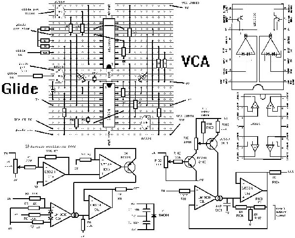
Down here it has been summer and too hot for soldering, but now that winter is on its way again I am once more thinking about keeping myself warm over that soldering iron. And I realised that last year I promised to upload my (very ordinary) linear VCA design, which has a bonus circuit on the side, my (slightly wacky) Sample and Hold and/or Glide. The sampling, holding and gliding is not as precise as one would expect from a proper S&H or Glide module, but it is definitely bit of fun. The CV input lets it glide when high and holds it when low. The transition voltage settable by pot P102. The other pot sets the glide rate. The hold is not that good, but would be better if you used a TL074 or similar. With the LM324 you can improve the hold performance with the bias R106-R108, but these aren't necessary otherwise.
Cheers,
Nicolas |
|
|
Back to top
|
|
 |
nicolas3141
Joined: May 25, 2007
Posts: 185
Location: Christchurch, New Zealand
|
|
|
Back to top
|
|
|
nicolas3141
Joined: May 25, 2007
Posts: 185
Location: Christchurch, New Zealand
|
| Posted: Sun May 09, 2010 12:47 am Post subject:
|
|
|
| Quote: | I'm just not sure if the glide is working or not. Could you please tell me what kind of configuration I should use to test it? I was thinking that for example if I put a slow moving square LFO into the input, I would get it gliding back and forth to the values rather than sharp corners, depending on the Glide Speed pot? Do you need a CV coming in for it to work? if so, what type? Please excuse my ignorance.. I'm just not sure if I built it wrong or am using it wrong  |
The glide has two inputs.
The input that goes to the LM13700 is the voltage that gets sampled
and held, or glided. Lets call that IN1.
The input that goes to the BC548 is like a switch. Lets call it IN2.
When that input is +1V or higher the thing samples or glides. Below
that voltage it holds. The cutoff voltage can be adjusted with P102.
To use it as a sample and hold set P101 to the bottom end that is connected to the BC548. When IN2 is high the thing samples and the output should match IN1. When IN2 goes back to zero volts (or less) the
output should hold and not change regardless of what is happening on
IN1. It may drift slowly, in which case you might want to experiment
with the three optional bias resistors to reduce that drift.
To use it as a glide module, connect IN2 to +6V or +9V and adjust P101
to set the glide rate. The output should match IN1, but if IN1
changes suddenly the output will only slowly catch up.
Once you have it working in these two modes, you can combine the two
ideas for glide and hold. Normally both inputs are fed CVs, but you
can do no harm if you want to experiment feeding them audio.
Cheers,
Nicolas |
|
|
Back to top
|
|
|
adambee7
Joined: Apr 04, 2009
Posts: 420
Location: united kingdom
|
| Posted: Sun May 09, 2010 12:59 am Post subject:
|
|
|
the vca is perfect for my lunetta. Thanks man for your input. Great circuits.  |
|
|
Back to top
|
|
|
DGTom

Joined: Dec 08, 2008
Posts: 211
Location: Adelaide
Audio files: 3
G2 patch files: 1
|
| Posted: Mon May 10, 2010 9:33 am Post subject:
|
|
|
Thankyou very much for this, I havn't tried the VCA yet as the idea of a dual "Glide & Hold" module made more sense for what I need at the moment.
Great little design. I used a TL072 for the output buffers & 13700... had abit of 'fun' with it until I discovered the transistors where backwards - some problems with Eagle BC objects 
Now its working the only "issue" I have is all the slew is up one end of the pot - its almost on/off, then all the way CW it totally turns off, none of the input makes it thru...
Should I use a LOG pot for the glide rate? or is this due to the fact i'm using +/-15V not +/-9V? Maybe I need to increase R103?
Once I iron out the kinks I think I'll build at least 1 or 2 more of these - super usefull |
|
|
Back to top
|
|
|
nicolas3141
Joined: May 25, 2007
Posts: 185
Location: Christchurch, New Zealand
|
| Posted: Mon May 10, 2010 2:03 pm Post subject:
|
|
|
Yes it may be a +/-15V issue. The log pot idea is good. Try that if you have one. It is possible that my prototype has a log pot, but I can't remember.
Other things to try are reduce R105 to 22k or similar and add a resistor in series between P101 and Q102 - try something in the range 47k to 120k.
Cheers,
Nicolas |
|
|
Back to top
|
|
|
DGTom
Joined: Dec 08, 2008
Posts: 211
Location: Adelaide
Audio files: 3
G2 patch files: 1
|
| Posted: Mon May 10, 2010 6:52 pm Post subject:
|
|
|
Thanks for the help, changed R105 to 22K & put a 100K in seris with the wiper of P101 & the base of Q101 & its working well now.
This is a really, really cool device! Feed it two differant CVs & you get cool sequences emerging that aren't quite one or the other but something in between. Of course it works well with straight gate signals into the control input, but, with actual sequences & the 2nd pot you can "pick out" certain notes to be held... really fun stuff, can't wait to get a few intermodulating one another  |
|
|
Back to top
|
|
|
Ojd
Joined: Feb 22, 2008
Posts: 66
Location: Ua
Audio files: 1
|
| Posted: Mon Jan 10, 2011 5:49 am Post subject:
|
|
|
| I'm sorry, can you tell what exactly R101 does? Maybe some reference to other people's design? I just cant grasp why there's pot before S&H trigger input? |
|
|
Back to top
|
|
|
nicolas3141
Joined: May 25, 2007
Posts: 185
Location: Christchurch, New Zealand
|
| Posted: Sat Jan 22, 2011 12:40 am Post subject:
|
|
|
Yes the pot (P102) is not necessary if you are going to be feeding it gate type pulses. If you want to feed it from an LFO, etc then the pot is helpful to set the level at which it triggers. But the circuit is simpler without it.
R101 on the input is probably also, as you say, unnecessary. I might have put it there to protect the LM13600 from anything crazy coming down the wire from other modules, but 100k seems way excessive. I would suggest leaving it out.
Thanks for pointing this out. Good to know someone is looking at things with their brain switched on
Cheers,
Nicolas |
|
|
Back to top
|
|
|
Ojd
Joined: Feb 22, 2008
Posts: 66
Location: Ua
Audio files: 1
|
| Posted: Thu Jan 27, 2011 9:06 am Post subject:
|
|
|
Ok, I'm confused now. Which one is the "smooth" (or lag) pot? 101 or 102?
I also came up with the idea of using tiny switch (i'm running out of panel space i'm afraid  ( ) to set 0V <-> +15V where is p102 in. Is it ok to use +15V on this input (seems pretty high), any possible damage to the LM13700? ( ) to set 0V <-> +15V where is p102 in. Is it ok to use +15V on this input (seems pretty high), any possible damage to the LM13700?
I'm at the final stages of building modular based on your schematics and designs (except noise, and polyvox vcf, which is THE simplest filter you can build (if you have access to soviet chips  )). Only one LFO left! )). Only one LFO left! |
|
|
Back to top
|
|
|
nicolas3141
Joined: May 25, 2007
Posts: 185
Location: Christchurch, New Zealand
|
| Posted: Thu Jan 27, 2011 12:23 pm Post subject:
|
|
|
P101 sets the glide rate and is important.
P102 can be left out, just connect R102 direct to the socket. If you are running it on +/-15V you might want to replace P102 with two resistors instead of leaving it out completely, say 22k to ground and 68k to socket. So then that little bit of the circuit would be:
node1 - 68k, 33k and 22k all connected together.
node2 - socket connected to other end of the 68k.
node3 - ground connected to other end of the 22k.
node4 - base of transistor connected to other end of the 33k.
cheers,
nicolas |
|
|
Back to top
|
|
|
glitched
Joined: Mar 25, 2006
Posts: 80
Location: phila., pa USA
|
| Posted: Mon Feb 07, 2011 10:55 pm Post subject:
|
|
|
Nicholas, you're the magician of economical circuits!
Would it be possible to compact this stripboard layout even further and get two VCAs out of it, instead of a VCA and a glide/s+h?
If I wanted a dual-VCA layout, is there a better configuration I should look for? |
|
|
Back to top
|
|
|
nicolas3141
Joined: May 25, 2007
Posts: 185
Location: Christchurch, New Zealand
|
|
|
Back to top
|
|
|
nicolas3141
Joined: May 25, 2007
Posts: 185
Location: Christchurch, New Zealand
|
| Posted: Tue Feb 08, 2011 3:18 am Post subject:
|
|
|
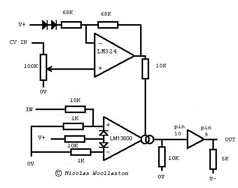
By the way, that circuit relies on your V+ and your V- being symmetrical either side of 0V. If that isn't perfectly true you may find that a 0V CV doesn't completely shut off the VCA. In that case you could try removing one of those diodes. By the way they should be 1N4148 or any similar diode. On the other hand if the VCA shuts off completely at a voltage above 0V, try adding a third diode.
Cheers,
Nicolas |
|
|
Back to top
|
|
|
nicolas3141
Joined: May 25, 2007
Posts: 185
Location: Christchurch, New Zealand
|
| Posted: Tue Feb 08, 2011 3:26 am Post subject:
|
|
|
Oh and one final thing - in the stripboard layout I have tied pin 10 of the LM13700 to V- because I originally was not using the LM13700 output buffer amplifiers. You will need to not do that and instead use the pin 10 to pin 9 amplifier for your output buffer. Hope you're not confused by all that
Cheers,
Nicolas |
|
|
Back to top
|
|
|
glitched
Joined: Mar 25, 2006
Posts: 80
Location: phila., pa USA
|
| Posted: Tue Feb 08, 2011 8:41 am Post subject:
|
|
|
You mean, connect pin 10 (output buffer) to pin 9 (input buffer) on the LM13600/700?
I'll definitely give this a try!
In the meantime, do you think it would be helpful to update the stripboard layout with this change? It might be helpful for some, but I think I'll be fine. (My problem has always been optimizing the layout, not exactly translating it.)
Thanks again.
Regards. |
|
|
Back to top
|
|
|
nicolas3141
Joined: May 25, 2007
Posts: 185
Location: Christchurch, New Zealand
|
| Posted: Tue Feb 08, 2011 1:56 pm Post subject:
|
|
|
No - connect pin12 to pin10 and also to a 10k resistor to ground.
Connect pin9 to a 1k resistor which goes to your output socket. Also connect pin9 to a 4.8k resistor which goes to V-.
Reading the datasheet for the LM13700 might make it clearer.
Cheers,
Nicolas |
|
|
Back to top
|
|
|
Gonecat
Joined: May 02, 2009
Posts: 43
Location: Rome, Italy
Audio files: 4
|
| Posted: Fri Oct 14, 2011 11:52 am Post subject:
|
|
|
Nicolas: Thanks for posting all your great designs. Perfect quick projects! They'll be a big help in finishing up my synth.
I have a few questions, if I'm able to revive this thread!
Is the diode that runs between V+ and V- not shown on the layout?
Any problems using TIS93 or 2N3906 in place of the BC559?
How about using 2n3904, MPSA18 or MPSA13 instead of the BC548?
Trying to build this soon as i can warm up the iron, so wanted to use parts that i have in stock.
Hope your street performances went well with your battery-op modulars!!! I used to busk in Europe a few moons ago,, though all acoustic. Fun stuff. |
|
|
Back to top
|
|
|
nicolas3141
Joined: May 25, 2007
Posts: 185
Location: Christchurch, New Zealand
|
| Posted: Wed Oct 19, 2011 12:14 pm Post subject:
|
|
|
The diode is a power protection type thing to protect against batteries getting inserted the wrong way round. May not be necessary in your situation, depending on connectors, etc. I don't think I have it on the board.
The transistors are not critical so you should be able to substitute anything reasonably similar.
Hope it does what you want
Nicolas |
|
|
Back to top
|
|
|
macumbista

Joined: Sep 12, 2007
Posts: 398
Location: berlin
Audio files: 3
|
| Posted: Sun Oct 30, 2011 9:01 am Post subject:
|
|
|
I was in the process of writing a post called "Simplest VCA in the World?", but then I found this one. Going to try it. I need a ton of simple, linear, DC coupled VCAs for a joystick-controlled 4x4 CV matrix mixer. This could fit the bill.
_________________
Esoteric drones and nonlinear distortion
Custom/handmade experimental instruments
macumbista.net |
|
|
Back to top
|
|
|
oculus
Joined: Oct 30, 2011
Posts: 35
Location: Iceland, Reykjavik
|
|
|
Back to top
|
|
|
nicolas3141
Joined: May 25, 2007
Posts: 185
Location: Christchurch, New Zealand
|
|
|
Back to top
|
|
|
Bogus Noise
Joined: Jun 03, 2009
Posts: 65
Location: Sheffield
|
| Posted: Sat Nov 03, 2012 6:07 am Post subject:
|
|
|
I've got one of these built up, but I have one problem I'm wondering about - it doesn't seem to work with a noise input.
I've built a standard little noise module with a 2n3904 and a TL072 (the other op amp is used to make a simultaneous pink noise output). Feeding a triangle wave LFO into the sample and hold and a pulse wave to trigger it works brilliantly, and I get a nice staircase wave on the output. But plugging the noise in just gives a voltage staying fairly close to 0v with slight wavering.
I've been checking things out on the oscilloscope, and both the triangle LFO and noise output are at similar levels and bipolar, so not sure why it's not sampling right.
Is this circuit suitable for feeding a noise signal in? Or should I build up a different unit for this application?
_________________
Circuit Bent Sonic Absurdity:
www.bogus-noise.co.uk
http://www.youtube.com/user/BogusNoise |
|
|
Back to top
|
|
|
nicolas3141
Joined: May 25, 2007
Posts: 185
Location: Christchurch, New Zealand
|
| Posted: Sat Nov 03, 2012 12:57 pm Post subject:
|
|
|
Not sure, but it might be that it is not sampling quickly enough. The pulse edge might not be instantaneous enough and/or the noise might have too much high frequency content. You might want to try filtering the noise a bit with a gentle lowpass filter and make sure the pulse is not getting filtered or slowed down in any way.
Nicolas |
|
|
Back to top
|
|
|
Bogus Noise
Joined: Jun 03, 2009
Posts: 65
Location: Sheffield
|
| Posted: Sun Nov 04, 2012 2:02 am Post subject:
|
|
|
Hi there, thanks for the reply!
I am triggering it with the square/pulse wave output of a Ray's Cool New LFO. I think the edges are pretty instantaneous, but I'll have a look on the oscilloscope and test it with the gate outs on a 4017 sequencer just to be sure.
I'd tested running the noise through a low pass/band pass module, but didn't get any luck with that as yet. I've also tried bypassing R101.
I'm presuming the LM13700 does the actual sample and holding, and IC1d is just for buffering the output? Is there anything I could change on the circuit to ensure a quicker sampling time? Maybe removing the glide pot altogether?
_________________
Circuit Bent Sonic Absurdity:
www.bogus-noise.co.uk
http://www.youtube.com/user/BogusNoise |
|
|
Back to top
|
|
|
|

 Forum index » DIY Hardware and Software