| Author |
Message |
adamon
Joined: May 15, 2009
Posts: 96
Location: Lawrence Kansas
Audio files: 3
|
 Posted: Wed Jul 07, 2010 3:31 pm Post subject:
An explanation about my "resistance controlled" system Posted: Wed Jul 07, 2010 3:31 pm Post subject:
An explanation about my "resistance controlled" system
Subject description: I use a lot of vactrols! |
  |
|
I've had several requests recently for me to explain a few of my new modules that I posted up here: http://electro-music.com/forum/topic-39579-275.html and I thought that I should first write up a little about my method for implementing control signals in my system as its a little different from the norm. I'm doing this with the hopes that I will be able to explain how my stuff works, and that others will be able to duplicate the overall functionality with the more standard means of utilizing control signals. I by no means claim to be the originator of any of the following, nor do I believe that this method is any better or worse than other standard methods. I simply started out with nothing, figured out how to make things work this way, and have stuck with it. I feel like its a "completely different yet basically the same" concept; just a different way of doing the same end result maybe.
So, with my system, rather than using direct voltage as a control, everything I use as a control gets coupled to a vactrol, and what I end up patching is resistors, rather than signals. Whenever I want a control input (say on a simple 40106 oscillator frequency pot) I make an option to choose to use either a pot, or to patch in the photocell end of a vactrol (I use two contact jacks, one contact is wired to each end of the photocell) (or I do other variations like putting the pot and jack in parallel so they are added). The vactrols end up being wired as the outputs of control modules (lfos, sequencers, ...). Wiring up the jacks this way makes it necessary to use non-conductive panels (I use 3.5mm switchcraft jacks) since the sleeve of the jack ends up being half of the resistor (photocell); hence my acrylic panels. (I'm sure if you used jacks that had isolated contacts, you could use metal panels...)
This setup has led to a lot of neat discoveries through the course of its development, and has ultimately made several things easier for me. Since everything is coupled through the vactrol, all of the level adjusting can be done internally within the vactrol (I make my own from different leds and photocells). I can choose different brightness leds and different ranges of photocells to make vactrols that "fit" specific applications. Due to my lack of technical knowledge in this field, it ends up being a lot of guess work and trial and error, but I'm getting better and better at it. Using this method of control has also allowed me to simplify a lot of circuits that I use; I don't have to worry much about any kind of vc input conditioning (like v/oct scaling inputs on vcos) since the conversion takes place in the vactrol; I mostly just deal with levels). I should mention also though that I'm not one to really care about accuracy or proper scaling at this point. I think matching the same precision scaling with this type of control coupling could be possible, I just don't really bother taking it that far (at this point...). I think overall, the best part (and easiest) of my setup is that whenever I see a new schematic, and I want to have external control over some aspect of it, as long as there's a pot somewhere, all I have to do is build a jack in with it, and then I've got my control (with some scaling/level adjusting).
So with that explanation, I feel it appropriate to now explain some of my modules in more detail. I'll be adding most of the explanations in other threads as they belong there more than here. I'll add links to them below as I post them.
_________________
www.soundcloud.com/adamon |
|
|
Back to top
|
|
 |
Rykhaard
Joined: Sep 02, 2007
Posts: 1290
Location: Canada
|
| Posted: Wed Jul 07, 2010 4:31 pm Post subject:
|
|
|
 THAT, is a very cool idea! Aye. The ways that you're implementing it can take values checking for things for their ranges / etc. But if you're not so much worried about that, that's a great way for controlling things that previous would require a bunch more stuff implemented! THAT, is a very cool idea! Aye. The ways that you're implementing it can take values checking for things for their ranges / etc. But if you're not so much worried about that, that's a great way for controlling things that previous would require a bunch more stuff implemented!
Now - I wish I had more than the 2 photocells that I picked up a couple of years ago. I've been keeping them to make my own vactrols.
Though! Here's a thought - I'd recently posted in the Development section at my Forum, the idea of driving a photocell with 2 individual LEDs! That way, the photocell would act as something of a 'mixer' to allow 2 different sources to control it's resistance! I haven't tried it yet, but am, looking forward to it. 
Another thought on it just now - 1 LED could be normal brightness and the other could be a superbright, for 2 different overall ranges, of control from the 1 photocell. |
|
|
Back to top
|
|
|
electri-fire
Joined: Jul 26, 2006
Posts: 536
Location: Dordrecht NL
Audio files: 4
G2 patch files: 4
|
| Posted: Thu Jul 08, 2010 3:01 am Post subject:
|
|
|
Exellent post Adamon, I second the use of vactrols as a means of controlling ANY resistor. Once adopted, the method requires no extra electronics knowledge or parts.
| Rykhaard wrote: | Here's a thought - I'd recently posted in the Development section at my Forum, the idea of driving a photocell with 2 individual LEDs! That way, the photocell would act as something of a 'mixer' to allow 2 different sources to control it's resistance! I haven't tried it yet, but am, looking forward to it.
Another thought on it just now - 1 LED could be normal brightness and the other could be a superbright, for 2 different overall ranges, of control from the 1 photocell. |
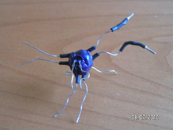
One LDR-multiple LEDs: works. One LED-multiple LDRs works as well. Here's one I built years ago for an abandoned project. Now waiting to be used for a quad voice "chorused" 40106 oscillator. Can you guess how I reminded myself what's the + lead? 
One LED with multiple LDR's trick: Put the LDRs in series for higher resistance, put them in parallel for lower resistance.
| Rykhaard wrote: | I wish I had more than the 2 photocells that I picked up a couple of years ago. I've been keeping them to make my own vactrols.
|
Prices vary enormously on ebay. http://shop.ebay.com/i.html?_nkw=ldr+photocell&_sacat=0&_odkw=ldr&_osacat=0&bkBtn=&_trksid=p3286.m270.l1313
I once had 100 miniature LDRs for 10 dollars and free shipping. No datasheet, but they turned out good.
| Description: |
| One LED quad LDR Vactrol. |
|
| Filesize: |
814.81 KB |
| Viewed: |
274 Time(s) |
| This image has been reduced to fit the page. Click on it to enlarge. |
|
|
|
|
Back to top
|
|
|
electri-fire
Joined: Jul 26, 2006
Posts: 536
Location: Dordrecht NL
Audio files: 4
G2 patch files: 4
|
| Posted: Thu Jul 08, 2010 5:24 am Post subject:
|
|
|
Remark: That quad-LDR vactrol was glued together with several layers of hotglue. The hotglue diffuses the light, so evens out the response, as not all LDRs have even contact to the LED.
Each hotglue layer was blackened with a marker,still some light gets through (also throuh the base of the LED that is not covered). The effect is slight enough to be ignored in dim lighting giving just a tiny humanising wobble. It can be used as a feature with bright lighting. |
|
|
Back to top
|
|
|
electri-fire
Joined: Jul 26, 2006
Posts: 536
Location: Dordrecht NL
Audio files: 4
G2 patch files: 4
|
|
|
Back to top
|
|
|
kkissinger
Stream Operator

Joined: Mar 28, 2006
Posts: 1471
Location: Kansas City, Mo USA
Audio files: 45
|
Posted: Thu Jul 08, 2010 7:27 am Post subject:
Re: An explanation about my "resistance controlled" system
Subject description: I use a lot of vactrols! |
|
|
| adamon wrote: | | I've had several requests recently for me to explain a few of my new modules that I posted up here: http://electro-music.com/forum/topic-39579-275.html and I thought that I should first write up a little about my method for implementing control signals in my system as its a little different from the norm. I'm doing this with the hopes that I will be able to explain how my stuff works, and that others will be able to duplicate the overall functionality with the more standard means of utilizing control signals. |
Awesome work, Damon!
This thread is very timely for me because I've run across an issue that can be addressed with vactrols.
Back in the late 70's, I built a foot pedal controller for my Aries synth. It consists of four independent pedals each with a small light and a cadmium cell. They are passive devices and are very effective.
However -- the cable run imparts noise to the signals -- and I've had an idea to use a vactrols on the synthesizer side. That is, the cadmium cell would control the brightness of an LED (vactrol) within the synthesizer so that no signal actually passes through the pedals.
Anyway, this is on my wish list.
In the meantime, I'll keep following this thread.
_________________
-- Kevin
http://kevinkissinger.com |
|
|
Back to top
|
|
|
adamon
Joined: May 15, 2009
Posts: 96
Location: Lawrence Kansas
Audio files: 3
|
| Posted: Thu Jul 08, 2010 8:21 am Post subject:
|
|
|
Thanks for the kind words everyone! As I said, I kind of just ran with it back when I first started building because it just made sense to me... good so far!
Rykhaard, as electri-fire pointed out, theres a ton of ways to get all sorts of different responses using home made vactrols. A while back someone posted this link for a "hairball" vactrol: http://www.musicsynthesizer.com/Hairball/hairball.html (looks very much like electri-fire's little device) As far as sizing and purchasing, I've found the rating table on smallbear's site helpful: http://www.smallbearelec.com/Detail.bok?no=711 You can find most of the same values on jameco as well. Up until recently my "method" for sizing things has been mostly to just get the photocell with the widest response possible, pair it with the brightest led I can (typically a bright white one), and then tone it down with an amount pot. I've recently started playing with different photocell types, and have definitely found that there can be huge differences in the pairings. I may be setting up some little experiments to try and sort through a bunch of different combinations of photocells and leds to get a better idea of what each's response is like.l
electri-fire, thats a good point about reducing resistance by pairing multiple photocells in parallel... I had really only thought about putting them in series... I may be using that soon for some new ideas!
Hey Kevin! Yeah, vactrols are a great way to "clean up" signal paths. I like the concept that my control lines and audio lines are completely separate; of course the original credit here is from buchla.
_________________
www.soundcloud.com/adamon |
|
|
Back to top
|
|
|
electri-fire
Joined: Jul 26, 2006
Posts: 536
Location: Dordrecht NL
Audio files: 4
G2 patch files: 4
|
|
|
Back to top
|
|
|
electri-fire
Joined: Jul 26, 2006
Posts: 536
Location: Dordrecht NL
Audio files: 4
G2 patch files: 4
|
| Posted: Sun Jul 11, 2010 9:21 am Post subject:
More LDR tricks |
|
|
For those opting for mechanical rather than electronic solutions:
More LDR tricks.
LDR too sensitive? A dab of paint, nailpolish, black marker, piece of paper, whatever on your LDR.
To reduce sensitivity to ambient light of a "wave your hand light theremin" situation: Have your LDR at the bottom of a tube.
A "wave your hand light theremin" voltage devider: A resistor (or potmeter) to ground, an LDR to +V (or some control voltage) , join these, the junction point will be the control voltage (or control voltage depth). |
|
|
Back to top
|
|
|
|

 Forum index » DIY Hardware and Software


