| Author |
Message |
Sebo

Joined: Apr 27, 2007
Posts: 564
Location: Argentina
|
 Posted: Sat Jan 05, 2013 5:32 pm Post subject: Posted: Sat Jan 05, 2013 5:32 pm Post subject:
|
  |
|
AC mixer means that can only accept AC signals, in practice the coupling is done by a high pass filter with a sub sonic cutoff frequency, so in general an AC mixer is considered capable of mix audio signals but not CV signals. Also an AC mixer will kill any DC that try to come in.
A DC mixer is suitable for any signal, audio and CV, and it will pass any DC.
I'm not sure to understand your last question, but if you will always use that path, your VCA could be AC or DC, don't really matters.
_________________
Sebo
---------------------------------------
My Music:
https://www.facebook.com/cosaquitos/ |
|
|
Back to top
|
|
 |
isak

Joined: Dec 13, 2009
Posts: 847
Location: Israel
Audio files: 18
|
| Posted: Sun Jan 06, 2013 12:06 am Post subject:
|
|
|
Understud, thank you for that!
I'll build the mixer and let you and the guys know if it worked for the Jorg ms20.
cheers.
_________________
http://www.myspace.com/mgmtrance |
|
|
Back to top
|
|
|
isak
Joined: Dec 13, 2009
Posts: 847
Location: Israel
Audio files: 18
|
| Posted: Wed Jan 09, 2013 4:36 am Post subject:
|
|
|
Hi Sebo.
I build the mixer and added 10uF Tantalums to all inputs like you adviced me.
The + side to the input, the - side to the resistors.
It's sound better now 
You where right about the vol input!
I lower the vol input in the mixer and the square and saw sound much much better.
One thing is still bothering me, the self osc is comming to soon when turning the reso pot CW, is there any way to make it start in about 3 o'clock?
Thanks Sebo.
Isak E.
_________________
http://www.myspace.com/mgmtrance |
|
|
Back to top
|
|
|
Sebo
Joined: Apr 27, 2007
Posts: 564
Location: Argentina
|
| Posted: Wed Jan 09, 2013 6:42 am Post subject:
|
|
|
Hi isak:
Great you get it sounding right!!!
I'm on vacation now, far away from home, I have to see the circuit to give you an answer. When I get back I'll check it out.
Cheers.
_________________
Sebo
---------------------------------------
My Music:
https://www.facebook.com/cosaquitos/ |
|
|
Back to top
|
|
|
isak
Joined: Dec 13, 2009
Posts: 847
Location: Israel
Audio files: 18
|
|
|
Back to top
|
|
|
feggster
Joined: Sep 12, 2011
Posts: 52
Location: uk
|
| Posted: Sat Jul 20, 2013 10:09 am Post subject:
|
|
|
hiya,
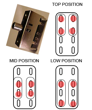
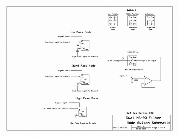
I built this and it works great (a few modifications to the layout to get it working) now I would like to add a 3 way switch to change LP HP BP
I have a slide switch (shown below) can anyone translate the wiring diagram for my switch...my brain hurts 
cheers.
| Description: |
|
| Filesize: |
45.58 KB |
| Viewed: |
48294 Time(s) |
|
| Description: |
|
| Filesize: |
51.82 KB |
| Viewed: |
1270 Time(s) |
| This image has been reduced to fit the page. Click on it to enlarge. |
|
|
|
|
Back to top
|
|
|
gila_crisis
Joined: Feb 06, 2014
Posts: 3
Location: Switzerland
|
| Posted: Thu Feb 06, 2014 3:33 pm Post subject:
|
|
|
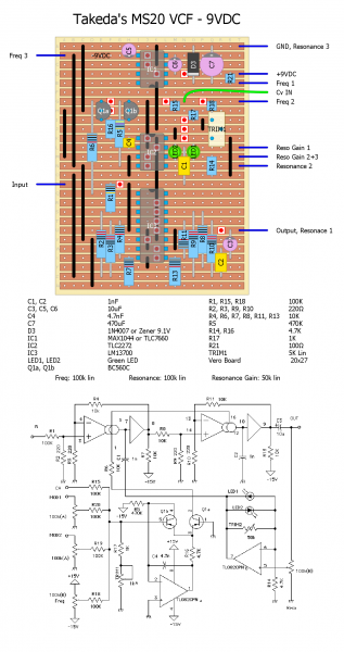
I built a MS20 VCF following this schematic I found on takeda's site:
http://www.aleph.co.jp/~takeda/radio/MS20clone.html
But I have a problem. I used a TLC2272 and a OPA2134 for the dual opamp, transistors are BC560c and I'm powering the circuit with a MAX1044, so that I can get +/-9VDC out of a normal 9V power supply.
I double checked everything and the voltages on the IC seams to be correct but it doesn't work right.
After a while the circuit is powered the sound starts to come out and for a while it works, but after a bit I noticed that with the freq fully turned down, the filter slowly opens! I measured the voltage on the circuit and I found out that on the collector of Q1a (as per takeda's schematic) the voltage slowly arise with the time, resulting in this "self opening" of the filter. Do you have any suggestion what the cause may be? |
|
|
Back to top
|
|
|
gila_crisis
Joined: Feb 06, 2014
Posts: 3
Location: Switzerland
|
| Posted: Thu Feb 06, 2014 4:07 pm Post subject:
|
|
|
I found the mistake.. I just forgotten to connect pin2 of the opamp with the 470k resistor going to -15VDC!
Now it works like a charme! I'll post the layout soon. |
|
|
Back to top
|
|
|
gila_crisis
Joined: Feb 06, 2014
Posts: 3
Location: Switzerland
|
|
|
Back to top
|
|
|
jmcecil
Joined: May 11, 2013
Posts: 20
Location: Prattville, AL
|
| Posted: Sun Feb 23, 2014 4:42 pm Post subject:
|
|
|
Sorry to resurrect the oldie, but I'm trying to use protoboard for the first time and this seemed like a fairly easy project. I ran into an issue though. trying to read the diagrams on the first page I find a jumper coming off the -15 and I can't figure out what it is for. Can someone explain please?

Also, the schematics are no longer at the link on the initial post. Would anyone have a link?
Thanks much |
|
|
Back to top
|
|
|
-minus-
Joined: Oct 26, 2008
Posts: 787
Audio files: 13
|
| Posted: Mon Feb 24, 2014 3:01 pm Post subject:
|
|
|
| I'd say that cut to the left of your long rectangle should not be there. If you have already cut this board, you will need to bridge that gap. You could use a piece of resistor leg and solder to the reverse side. Or you could swap R6 and the jumper, then bridge the gap with a three hole horizontal jumper to take the (-)V to pin 11 of the TL074. |
|
|
Back to top
|
|
|
jmcecil
Joined: May 11, 2013
Posts: 20
Location: Prattville, AL
|
| Posted: Mon Feb 24, 2014 6:33 pm Post subject:
|
|
|
| -minus- wrote: | | I'd say that cut to the left of your long rectangle should not be there. If you have already cut this board, you will need to bridge that gap. You could use a piece of resistor leg and solder to the reverse side. Or you could swap R6 and the jumper, then bridge the gap with a three hole horizontal jumper to take the (-)V to pin 11 of the TL074. |
hey thanks, that actually makes sense. It's odd because that is the graphic from page 1. If it obviously that wrong, I'm surprised I don't see anyone pointing it out. |
|
|
Back to top
|
|
|
roglok

Joined: Aug 28, 2010
Posts: 202
Location: uptown
|
| Posted: Tue Feb 25, 2014 1:38 am Post subject:
|
|
|
| jmcecil wrote: | | -minus- wrote: | | I'd say that cut to the left of your long rectangle should not be there. If you have already cut this board, you will need to bridge that gap. You could use a piece of resistor leg and solder to the reverse side. Or you could swap R6 and the jumper, then bridge the gap with a three hole horizontal jumper to take the (-)V to pin 11 of the TL074. |
hey thanks, that actually makes sense. It's odd because that is the graphic from page 1. If it obviously that wrong, I'm surprised I don't see anyone pointing it out. |
pointed out here already:
http://electro-music.com/forum/post-341471.html#341471
cheers! |
|
|
Back to top
|
|
|
jmcecil
Joined: May 11, 2013
Posts: 20
Location: Prattville, AL
|
| Posted: Wed Feb 26, 2014 5:27 am Post subject:
|
|
|
| roglok wrote: | | jmcecil wrote: | | -minus- wrote: | | I'd say that cut to the left of your long rectangle should not be there. If you have already cut this board, you will need to bridge that gap. You could use a piece of resistor leg and solder to the reverse side. Or you could swap R6 and the jumper, then bridge the gap with a three hole horizontal jumper to take the (-)V to pin 11 of the TL074. |
hey thanks, that actually makes sense. It's odd because that is the graphic from page 1. If it obviously that wrong, I'm surprised I don't see anyone pointing it out. |
pointed out here already:
http://electro-music.com/forum/post-341471.html#341471
cheers! |
crap, right under my nose. Thank you! |
|
|
Back to top
|
|
|
Fahz0r
Joined: Jul 20, 2014
Posts: 1
Location: Netherlands
|
|
|
Back to top
|
|
|
Snaper
Joined: Feb 28, 2014
Posts: 217
Location: Hungary
|
| Posted: Sat Aug 02, 2014 12:32 pm Post subject:
|
|
|
The +/- jumpers should be switched on tl074.
Pin 4 to -, pin 12 to + |
|
|
Back to top
|
|
|
hoyager
Joined: Feb 16, 2010
Posts: 27
Location: New Zealand
|
| Posted: Tue Aug 05, 2014 5:24 pm Post subject:
|
|
|
| Snaper wrote: | The +/- jumpers should be switched on tl074.
Pin 4 to -, pin 12 to + |
Google tl074 images

LM13700 is opposite but correct in the last updated layout |
|
|
Back to top
|
|
|
Snaper
Joined: Feb 28, 2014
Posts: 217
Location: Hungary
|
| Posted: Tue Aug 05, 2014 8:18 pm Post subject:
|
|
|
| hoyager wrote: | | Snaper wrote: | The +/- jumpers should be switched on tl074.
Pin 4 to -, pin 12 to + |
Google tl074 images
LM13700 is opposite but correct in the last updated layout |
Wow, thats right, sorry. |
|
|
Back to top
|
|
|
hoyager
Joined: Feb 16, 2010
Posts: 27
Location: New Zealand
|
| Posted: Tue Aug 05, 2014 9:57 pm Post subject:
|
|
|
Cool, it seems people are starting out building stuff by using this, which I did, so thought it'd better not be misleading
Here's some mods I do on this circuit to keep the res under control, overdrive the input a bit and get the freq pot to behave with a full range.
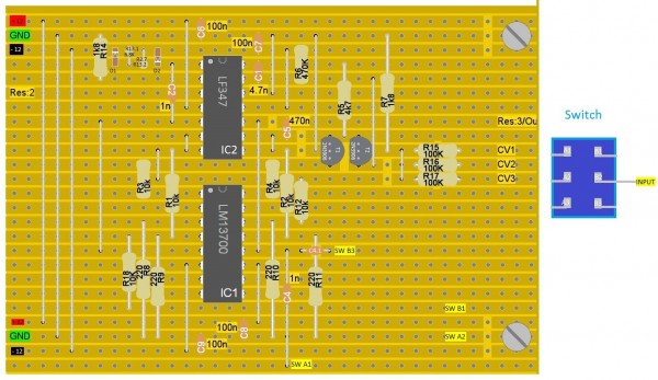
On the last layout posted - lm13700_MSfilter_Fix.jpg
1. Make R7 2.2k and the link to ground on the opposite transistor, 2.2k as well (as per ms20). So both transistor bases go to ground via a 2.2k.
2. Make the CV resistor from the Freq (cutoff) pot 300k and make R3 and R4, 7.5k (Or don't cut under pins 1 and 16 of LM13700 and use 1 7.5k resistor to both pins).
2a. Use 47n in place of c1 to cut down on some cv bleedthrough (rounds corners of square wav if an lfo is used) - not necessary for manual cutoff control
3. R14 make 2.7k (or 5k trimpot) for self oscillation later in the travel of the res knob and make the res knob 10kb, put a 2.2k resistor across lug 2 + 3, and use an 8.2k resistor from the res3/out to the lug 3 of res pot (as per ms20)
3a. Use 3 1n4148 in series in each direction and 10k in the feedback loop for res opamp (between pins 1 and 2) (as per ms20). I use 1s1555 which are what they used in the original. I think have a different forward voltage curve (going higher than 1n4148 but at a lower rate....) Anyway I think they break up a bit nicer and sound a bit more garbly. This might be due to them being more uneven in forward voltage drop than modern manufactured 1n4148, but again I don't really know.
4. Use a polar 10uf cap for c5 (+ side at - input (pin 9 of TL074))
5. Low pass input resistor R18 make 7.5k for more overdrive and add a 47k resistor from the hi pass input (gnd end of C4) to gnd .This will tie the cap to ground when there is no input, eliminating some switching complexity, although this might require make before break for click-less switching)
6. Lofi opamp like LM348 works well too (along with LF347) can overdrive filter without clipping. I found the TL074 or 072 will shutdown in this situation as buffers if there is too much input (has to be quite a lot, but filter does sound good with quite a lot of input)
7. I use 2.2n's for C2 and C4, and compensate for high freq loss (only very high freq) with 2.2n and 470k in series in feedback loop of an output opamp. If you want a mellower filter just use 2.2n's.
Also in the this last layout, I think the diodes and resistors D1 D2 R13.1+2 are supposed to be 1 line down so they are across pins 1 and 2 of the opamp.
Andy |
|
|
Back to top
|
|
|
Snaper
Joined: Feb 28, 2014
Posts: 217
Location: Hungary
|
| Posted: Tue Aug 05, 2014 10:25 pm Post subject:
|
|
|
| hoyager wrote: | Cool, it seems people are starting out building stuff by using this, which I did, so thought it'd better not be misleading
Here's some mods I do on this circuit to keep the res under control, overdrive the input a bit and get the freq pot to behave with a full range.
On the last layout posted - lm13700_MSfilter_Fix.jpg
1. Make R7 2.2k and the link to ground on the opposite transistor, 2.2k as well (as per ms20). So both transistor bases go to ground via a 2.2k.
2. Make the CV resistor from the Freq (cutoff) pot 300k and make R3 and R4, 7.5k (Or don't cut under pins 1 and 16 of LM13700 and use 1 7.5k resistor to both pins).
2a. Use 47n in place of c1 to cut down on some cv bleedthrough (rounds corners of square wav if an lfo is used) - not necessary for manual cutoff control
3. R14 make 2.7k (or 5k trimpot) for self oscillation later in the travel of the res knob and make the res knob 10kb, put a 2.2k resistor across lug 2 + 3, and use an 8.2k resistor from the res3/out to the lug 3 of res pot (as per ms20)
3a. Use 3 1n4148 in series in each direction and 10k in the feedback loop for res opamp (between pins 1 and 2) (as per ms20). I use 1s1555 which are what they used in the original. I think have a different forward voltage curve (going higher than 1n4148 but at a lower rate....) Anyway I think they break up a bit nicer and sound a bit more garbly. This might be due to them being more uneven in forward voltage drop than modern manufactured 1n4148, but again I don't really know.
4. Use a polar 10uf cap for c5 (+ side at - input (pin 9 of TL074))
5. Low pass input resistor R18 make 7.5k for more overdrive and add a 47k resistor from the hi pass input (gnd end of C4) to gnd .This will tie the cap to ground when there is no input, eliminating some switching complexity, although this might require make before break for click-less switching)
6. Lofi opamp like LM348 works well too (along with LF347) can overdrive filter without clipping. I found the TL074 or 072 will shutdown in this situation as buffers if there is too much input (has to be quite a lot, but filter does sound good with quite a lot of input)
7. I use 2.2n's for C2 and C4, and compensate for high freq loss (only very high freq) with 2.2n and 470k in series in feedback loop of an output opamp. If you want a mellower filter just use 2.2n's.
Also in the this last layout, I think the diodes and resistors D1 D2 R13.1+2 are supposed to be 1 line down so they are across pins 1 and 2 of the opamp.
Andy |
Do you have an udated layout for this version?
Would be good  |
|
|
Back to top
|
|
|
hoyager
Joined: Feb 16, 2010
Posts: 27
Location: New Zealand
|
| Posted: Wed Aug 06, 2014 12:15 am Post subject:
|
|
|
No sorry, just as the last layout that was posted by someone else is plus these changes.
Shouldn't be too hard to follow, I tried to make it as clear as I could. You could recreate the existing layout with diylc (google it, its free) and add in the changes.
Andy |
|
|
Back to top
|
|
|
wackelpeter
Joined: May 05, 2013
Posts: 461
Location: germany
Audio files: 10
|
| Posted: Fri Sep 05, 2014 12:07 am Post subject:
|
|
|
Maybe this will be of interest for someone...
I've recently built 2 of These ms20 VCF's with the lm13700 but the second one didn't want to oscillate properly...
following Rene's schematics i've used the latter suggested design (mostly what Hoyager did) with 2,2n caps instead of 1n, and with the 8,2k and 2,2k resistors placed at the reso-pot.
also i used a 1,8k resistor and 5k trimmpot to the inverting Input of the Feedback stage of the opamp...
the resistor of the summing stage after the freq-pot is 150k and the resistor to gnd at the base of the trannie is 680 ohms instead of 1,8K.
the Output cap is 22uF instead of 0,47 and reso pot is 10k...
Also added is a pot for the Input Signal.
That said my first filter worked very well but the second wont oscillate or just with a minimal effect on Sound when reso is turned fully on...
checked the 2nd one a couple of times but couldn't find the mistake... then compared it with the first one and found that on the first one i accidentally reversed 2 of the Diodes in the Feedback path...
I used the design with 2 rows of 3 diodes...
when you revert one of them in each row you get a very cool sounding effect... just using link instead of 2 diodes in each row didn't work for that...
maybe some of you want to try this "trick" with the diodes it sounds really good...
_________________
https://soundcloud.com/bastian-j |
|
|
Back to top
|
|
|
Thelonious
Joined: Mar 03, 2015
Posts: 5
Location: France
|
| Posted: Tue Mar 03, 2015 4:02 pm Post subject:
|
|
|
Hi,
I project to make this MS20 filter clone, so I do a new vero layout (smaller, and without the mistakes). I'll post it very soon.
But I don't understand why there are these 100nF (C6 to C9) between +15 -15V and ground, and why put it 2 times ? They are not present in the schematic.
Thanks
It's an old post, hope someone follow it yet. |
|
|
Back to top
|
|
|
Snaper
Joined: Feb 28, 2014
Posts: 217
Location: Hungary
|
| Posted: Tue Mar 03, 2015 8:14 pm Post subject:
|
|
|
| I think they are fot stabilizing the power. I usually add 2 10u and 2 100n. |
|
|
Back to top
|
|
|
Thelonious
Joined: Mar 03, 2015
Posts: 5
Location: France
|
| Posted: Wed Mar 04, 2015 4:15 pm Post subject:
|
|
|
Ok thanks snaper.
I finish my layout.
I made 2 versions, one "normal" and one with hoyager's mods.
But I have some questions.
For the "normal" version :
What is the value of C4.1 ?
Switch A1 and A2 are connect to ground, and A3 without connection ?
The DPDT is ON-ON (B1 is Lowpass input, and B3 is Highpass input) ?
For the hoyager version :
Don't understand this : "use an 8.2k resistor from the res3/out to the lug 3 of res pot (as per ms20) " ? (It's a bit confused)
And this : "add a 47k resistor from the hi pass input (gnd end of C4) to gnd ." ? (If I understand, he want to put a 47k in serie with C4 before to go to ground).
I can send you my layouts if you want.
Thanks |
|
|
Back to top
|
|
|
|

 Forum index » DIY Hardware and Software » The layout factory