| Author |
Message |
Kritical Audio
Joined: Jul 17, 2010
Posts: 3
Location: Sweden
|
 Posted: Sat Jul 17, 2010 5:45 pm Post subject:
MS-20 (LM-13700 version),Polivoks or EMS VCF on veroboard? Posted: Sat Jul 17, 2010 5:45 pm Post subject:
MS-20 (LM-13700 version),Polivoks or EMS VCF on veroboard? |
  |
|
Hi!
Does anyone here got a veroboard layout for any of these? I've been looking everywhere and I thought I'd ask you kind folks here 
Would be great if someone could help me out!
Cheers,
/KA |
|
|
Back to top
|
|
 |
Clack

Joined: Aug 08, 2005
Posts: 438
Location: Walthamstow - london
Audio files: 5
G2 patch files: 1
|
| Posted: Mon Jul 19, 2010 6:01 am Post subject:
|
|
|
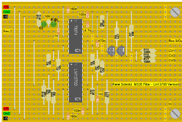
Funny I was just working on this one by René Schmitz
http://www.uni-bonn.de/~uzs159/rs20.png
It doesnt have any de-coupling caps and I havnt tested it yet but your welcome to have a go, not everything is labelled but I can get back to you on that -Ben
[Removed see further down post]
_________________
Clacktronics.co.uk
Last edited by Clack on Thu Nov 04, 2010 4:07 am; edited 1 time in total |
|
|
Back to top
|
|
|
Kritical Audio
Joined: Jul 17, 2010
Posts: 3
Location: Sweden
|
| Posted: Mon Jul 19, 2010 11:30 am Post subject:
|
|
|
Cheers for that! Now I have to order parts for this, so it would be great if you could label the components! Should the de-coupling caps be in there? I'm a newbee on this stuff...
Thanks again!
/KA |
|
|
Back to top
|
|
|
Clack
Joined: Aug 08, 2005
Posts: 438
Location: Walthamstow - london
Audio files: 5
G2 patch files: 1
|
| Posted: Thu Nov 04, 2010 4:17 am Post subject:
|
|
|
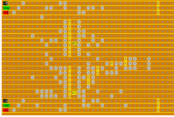
Sorry if its to late but here it is - still not tested - but I can confirm it soon
Panel Potentiometers
if viewed from the back and lugs counted 1 to 3 connections go like this
Resonance 100K LOG
1 Res:3 - Output jack connect to this lug
2 Res:2
3 GND
Cutoff 4.7K LIN
1 -15
2 -CV1
3 +15
Jacks
Input connects to in
Output connects to pot 1 lug 1
extra cv jacks on CV2 and CV3
a 4,7k potentiometer can be connected across the cv inputs to attenuate it like so
1 - GND
2 - CV1 or 2
3 - CV input jack
Schematic found here http://www.uni-bonn.de/~uzs159/
| Description: |
|
| Filesize: |
373.88 KB |
| Viewed: |
3795 Time(s) |
| This image has been reduced to fit the page. Click on it to enlarge. |
|
| Description: |
|
| Filesize: |
412.82 KB |
| Viewed: |
1876 Time(s) |
| This image has been reduced to fit the page. Click on it to enlarge. |
|
_________________
Clacktronics.co.uk |
|
|
Back to top
|
|
|
Kritical Audio
Joined: Jul 17, 2010
Posts: 3
Location: Sweden
|
| Posted: Thu Nov 04, 2010 4:56 am Post subject:
|
|
|
| Cheers! Just hope it works now! D1 and D2 is 0.47uf am I right? |
|
|
Back to top
|
|
|
mark_olson
Joined: Oct 26, 2006
Posts: 177
Location: Lawrence, Kansas
|
| Posted: Thu Nov 04, 2010 6:47 am Post subject:
|
|
|
| Kritical Audio wrote: | | D1 and D2...? |
Green LEDs. |
|
|
Back to top
|
|
|
Clack
Joined: Aug 08, 2005
Posts: 438
Location: Walthamstow - london
Audio files: 5
G2 patch files: 1
|
| Posted: Sat Nov 06, 2010 3:58 pm Post subject:
|
|
|
yes sorry they are green LED's , you can use pretty much any standard signal (1n914, 1n4148 etc) diode though, still trying out how to make lochmaster do clean layouts, might start translating them in illustrator so I can stylize them better. let me know if you get it to work! mine isn't up for soldering for a few weeks as I have to get a vco to work first! -Ben
_________________
Clacktronics.co.uk |
|
|
Back to top
|
|
|
JRock
Joined: Mar 05, 2010
Posts: 87
Location: Bucks County, PA
Audio files: 1
|
| Posted: Sat Dec 04, 2010 7:52 pm Post subject:
|
|
|
| Will this work with v/oct? Or is it Hz/Oct? |
|
|
Back to top
|
|
|
-minus-
Joined: Oct 26, 2008
Posts: 787
Audio files: 13
|
| Posted: Sat Jan 01, 2011 8:14 am Post subject:
|
|
|
| Any confirmation yet? I'm thinking there are meant to be cuts under the three resistors, R15 R16 R17... and one too many solder points on the three hole jumper beside them. |
|
|
Back to top
|
|
|
sohcahtoa

Joined: Aug 12, 2006
Posts: 55
Location: Fargo, ND
|
| Posted: Tue Mar 29, 2011 7:55 pm Post subject:
|
|
|
| @JROCK this filter has no effect on the octave question you posed, it's both. |
|
|
Back to top
|
|
|
JRock
Joined: Mar 05, 2010
Posts: 87
Location: Bucks County, PA
Audio files: 1
|
| Posted: Tue Mar 29, 2011 8:04 pm Post subject:
|
|
|
Thanks  |
|
|
Back to top
|
|
|
jmejia
Joined: Mar 12, 2009
Posts: 114
Location: portland
|
| Posted: Mon Apr 04, 2011 5:16 pm Post subject:
|
|
|
| So the 13700 works as a dropin replacement for the ca3080 in this circuit? Or does it require some changes? Do you have a schematic drawn out of your version? (unless it's the same as Rene's....) |
|
|
Back to top
|
|
|
Clack
Joined: Aug 08, 2005
Posts: 438
Location: Walthamstow - london
Audio files: 5
G2 patch files: 1
|
| Posted: Tue Apr 05, 2011 12:29 am Post subject:
|
|
|
You can drop in a LM13700 pretty much anywhere a 3080 is, In fact I think they work a little better in a filter like this as the 2 OTA stages are matched inside the IC.
I will try build this soon
_________________
Clacktronics.co.uk |
|
|
Back to top
|
|
|
hoyager
Joined: Feb 16, 2010
Posts: 27
Location: New Zealand
|
| Posted: Fri May 20, 2011 1:16 am Post subject:
|
|
|
Any progress with this filter? a working example anyone?
I am going to build it, just i've built a wsG filter and a 13700 MS20 9v, both which don't work properly, which could be me, but i don't know enough to know where or if there is an error with the layouts...
Andy |
|
|
Back to top
|
|
|
snebenan
Joined: Oct 03, 2010
Posts: 13
Location: Sweden
|
| Posted: Tue May 24, 2011 12:23 am Post subject:
|
|
|
Should there not be a cut between the two transistors bases as well?
//s |
|
|
Back to top
|
|
|
hoyager
Joined: Feb 16, 2010
Posts: 27
Location: New Zealand
|
| Posted: Mon Oct 03, 2011 3:00 am Post subject:
|
|
|
Hey, I've built this with the cuts between the 2 transistors and between the cv resistors, and have also soldered in the base of one of the transistors where on the layout it is floating.
I am wondering if someone who knows can verify these possible errors, if they are?
I've used a charge doubler with 15v regulator and voltage inverter to get +14.55v ground and -14.35v
This should be within range? or does it need to be exactly -15 and +15?
All I get on the output is a quiet whine which gets lower in pitch from when the power is plugged in, then nothing, no output at all, and the leds aren't lighting up either..
Also the pots are connected if looking down on the shaft 1 2 3 L to R
The description says from the back 1 to 3, is that L to R?, and if so have I just reversed the wiring to the pots? It should still work though, in that case? just have opposite control?
Also I've grounded the jacks, but i can't imagine that they should be without grounds?


And can anyone tell me if the power needs to be connected to the board as well as the freq pot?
Have used a TL084 instead of 074, but that shouldn't be a problem afaik.
Sorry for all the questions
Andy |
|
|
Back to top
|
|
|
hoyager
Joined: Feb 16, 2010
Posts: 27
Location: New Zealand
|
| Posted: Mon Oct 03, 2011 10:58 pm Post subject:
|
|
|
OK sussed it, funny how the act of asking somehow brings a solution on its own. There is not supposed to be a cut on the layout between pin 11 (TL074) Vee (-15) and the jumper to -15v, which should get the -15 to the chip.
I've used red leds, and the resonance is too much at low settings so I *think* the 10k resistor in the feedback loop needs to be lower? Or I might string 1n4001 diodes to lower clipping level.
Also the BC558's need to be reversed. I've used 2n3906's too which will work orientated the way shown in the layout.
This as well as the cut between the 2 transistor bases and between the cv resistors (just incase for anyone in the same boat as I was building)
Thanks for doing the layout Clack
Choice one
Andy |
|
|
Back to top
|
|
|
Clack
Joined: Aug 08, 2005
Posts: 438
Location: Walthamstow - london
Audio files: 5
G2 patch files: 1
|
| Posted: Tue Oct 04, 2011 2:19 am Post subject:
|
|
|
Hey thats good! no problem. Wow big caps!
Looking at it the LED's are a bit close aren't they!
I will update the layout , how does it sound?
-Ben
_________________
Clacktronics.co.uk |
|
|
Back to top
|
|
|
hoyager
Joined: Feb 16, 2010
Posts: 27
Location: New Zealand
|
| Posted: Tue Oct 04, 2011 3:46 am Post subject:
|
|
|
Sounds good, but way too much res at this stage. I think its more usable, as an effects box to have no gain drop when no res is used and the res taking the output only a little higher than unity when cranked. Will update with mods
Andy |
|
|
Back to top
|
|
|
Paradigm X
Joined: Feb 15, 2011
Posts: 363
Location: Null and void
Audio files: 2
|
| Posted: Wed Oct 05, 2011 3:20 am Post subject:
|
|
|
Cool, thanks for posting this. 
Will it work at +/-12v do you know, or what mods are required?
Is there a rule of thrumb for converting between the two i should know about 
Cheers
Ben |
|
|
Back to top
|
|
|
hoyager
Joined: Feb 16, 2010
Posts: 27
Location: New Zealand
|
| Posted: Sat Oct 08, 2011 9:46 pm Post subject:
|
|
|
| Should be totally fine on 12v, just lower headroom? this is as far as I know |
|
|
Back to top
|
|
|
synthesist
Joined: Feb 17, 2011
Posts: 79
Location: austria
Audio files: 2
|
| Posted: Sat Oct 15, 2011 2:52 am Post subject:
|
|
|
awesome!!!
I build the filter yesterday...took me more than 2 hours.
Result: I love it!
I used a 10k pot for the cut off, but I think it doesnt matter what value you use, since it's a voltage divider anyway, or?
I used green leds and I really like the strong self resonance. You can use it as a sine wave oscillator too.
Thanks a lot for the layout clack. I am sure the positon of the two 558- transistors on the stripboard is correct though. It also matches the circuit layout from rene schmitz.
By the way, mine is powered by two 9 volt batteries and it works just fine. |
|
|
Back to top
|
|
|
hoyager
Joined: Feb 16, 2010
Posts: 27
Location: New Zealand
|
| Posted: Sat Oct 15, 2011 3:03 am Post subject:
|
|
|
Cool, I put a 1k resistor in parallel to the 1k8 at r7 to get more response from a 5k pot. The pot value doesn't seem to matter as much as that resistor.
Regarding the freq pot |
|
|
Back to top
|
|
|
citric acid

Joined: Jun 11, 2011
Posts: 45
Location: germany
|
| Posted: Sat Oct 15, 2011 11:20 am Post subject:
|
|
|
| Clack wrote: | Hey thats good! no problem. Wow big caps!
Looking at it the LED's are a bit close aren't they!
I will update the layout , how does it sound?
-Ben |
hi ben,
have you an updated version ?
that will be verry nice.
thanks,
cit
_________________
http://soundcloud.com/citric-acid-303 |
|
|
Back to top
|
|
|
philoop
Joined: Aug 19, 2011
Posts: 15
Location: hamburg
|
Posted: Sun Oct 16, 2011 6:51 am Post subject:
ms20 filter
Subject description: Lp Hp |
|
|
well this is really nice ...but its only one half of the ms20 filter.
someone has a highpass version? |
|
|
Back to top
|
|
|
|

 Forum index » DIY Hardware and Software » The layout factory
