| Author |
Message |
isak

Joined: Dec 13, 2009
Posts: 847
Location: Israel
Audio files: 18
|
 Posted: Wed Jan 02, 2013 2:24 am Post subject:
ms20 Jorg schmitz layout Posted: Wed Jan 02, 2013 2:24 am Post subject:
ms20 Jorg schmitz layout |
  |
|
i was wandering if you guys can help me with something please.
from the next layout..
http://www.analog-synth.de/synths/mod2/ms20filter/rene_ms20_filter_clone%20rev%204.pdf
build it and i'm not sure about the sound, i dont have an ms20, never had one, so i really dont know if its came out ok.
i attached the sound demos for you to hear, can you please tell if its sounds like yours?
used -/+15V
green leds.
Saw wave from the Odyssey VCO (Andy1960 layout).
first demo - reso is at 12 o'clock.
second demo - reso is at 3 o'clock
third demo - reso is all the way up.
please tell me if the reso is ok and its sound like the original.
i thank you in advance.
cheers,
Isak E.
| Description: |
|

Download (listen) |
| Filename: |
12 oclock reso.wav |
| Filesize: |
850.82 KB |
| Downloaded: |
1226 Time(s) |
| Description: |
|
Download (listen) |
| Filename: |
3 oclock reso.wav |
| Filesize: |
1015.08 KB |
| Downloaded: |
1209 Time(s) |
| Description: |
|
Download (listen) |
| Filename: |
reso all the way up.wav |
| Filesize: |
1.57 MB |
| Downloaded: |
1235 Time(s) |
_________________
http://www.myspace.com/mgmtrance |
|
|
Back to top
|
|
 |
LektroiD

Joined: Aug 23, 2008
Posts: 1019
Location: Scottish Borders
Audio files: 2
G2 patch files: 2
|
| Posted: Thu Jan 03, 2013 7:58 am Post subject:
|
|
|
I can't help with the sound comparison (although going by memory, it sounds very familiar). I would however, be interested to know if it's easy to adapt this into the elusive MS20 HPF?
_________________
LektroiD |
|
|
Back to top
|
|
|
isak
Joined: Dec 13, 2009
Posts: 847
Location: Israel
Audio files: 18
|
| Posted: Thu Jan 03, 2013 8:18 am Post subject:
|
|
|
Very easily.
Lock at the first link I uploaded.
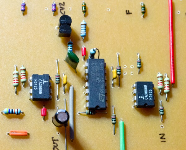
Now, you see the 1nF blow the upper 3080?
Take the right pin of this cap out and connect the sound source (vco) to that pin, that's it, you got HP 
cheers.
_________________
http://www.myspace.com/mgmtrance |
|
|
Back to top
|
|
|
LektroiD
Joined: Aug 23, 2008
Posts: 1019
Location: Scottish Borders
Audio files: 2
G2 patch files: 2
|
| Posted: Thu Jan 03, 2013 3:48 pm Post subject:
|
|
|
Simple enough to make it switchable then... I'm now wondering if there's a bandpass (or notch) on the board to tap into...
_________________
LektroiD |
|
|
Back to top
|
|
|
isak
Joined: Dec 13, 2009
Posts: 847
Location: Israel
Audio files: 18
|
|
|
Back to top
|
|
|
LektroiD
Joined: Aug 23, 2008
Posts: 1019
Location: Scottish Borders
Audio files: 2
G2 patch files: 2
|
| Posted: Fri Jan 04, 2013 2:33 am Post subject:
|
|
|
Ace. I wonder how to wire the switch when the capacitor leg is lifted for the HP, then reconnect the leg for the LP..
Also, What do the LEDs do (I've not seen LEDs on a filter before)... Should I bring them to the front panel?
There is one more question, the .47µF capacitor, is it polarised? Which orientation? I have an Electrolytic with the positive going to the output...
I also noticed some mismatches with the PCB and the schematic. On the PCB, it seems the resistor at CV1 is 22K, the resistor at CV2 is 100K.. There is also a 22K between the two CV's going nowhere?
Many thanks for posting this, it's a fun little project
_________________
LektroiD |
|
|
Back to top
|
|
|
isak
Joined: Dec 13, 2009
Posts: 847
Location: Israel
Audio files: 18
|
| Posted: Fri Jan 04, 2013 4:20 am Post subject:
|
|
|
The .47uF is poly, no polarity.
I put 100k to all,like the original scheme says, didn't check it tho..
before going further with this project I want to make sure the sound I get is correct.
please pay attantion to the next post..(roll down a bit)
http://electro-music.com/forum/post-375902.html#375902
important info Sebo is giving me there
_________________
http://www.myspace.com/mgmtrance |
|
|
Back to top
|
|
|
isak
Joined: Dec 13, 2009
Posts: 847
Location: Israel
Audio files: 18
|
| Posted: Fri Jan 04, 2013 8:19 am Post subject:
|
|
|
BTW...
More important note.
When on LP mode right pin of 1nF need to be connected.
When on HP right pin of 1nF need to be disconnected and act as the input.
So you will need a 6 pin on & on switch.
One operation to move from LP to HP, second operation to connect and disconnect right pin of 1nF.
_________________
http://www.myspace.com/mgmtrance |
|
|
Back to top
|
|
|
steffensen

Joined: Jul 11, 2012
Posts: 103
Location: Sweden
|
| Posted: Tue Jan 08, 2013 1:27 pm Post subject:
|
|
|
| I too can only judge from memory, and i do hear the MS-20 vibe goin on here. Good work my friend! Sounds awesome. |
|
|
Back to top
|
|
|
isak
Joined: Dec 13, 2009
Posts: 847
Location: Israel
Audio files: 18
|
|
|
Back to top
|
|
|
LektroiD
Joined: Aug 23, 2008
Posts: 1019
Location: Scottish Borders
Audio files: 2
G2 patch files: 2
|
| Posted: Thu Jan 10, 2013 5:40 pm Post subject:
|
|
|
I built it, initially wiring up the power backwards, but since replaced the 2x CA3080's and the TL074, and it doesn't work... It seems to make a bandpass effect when I wire the in to the out and vice versa, but in the normal configuration I get nothing except a small amount of random noise...
What else might have popped?
_________________
LektroiD |
|
|
Back to top
|
|
|
isak
Joined: Dec 13, 2009
Posts: 847
Location: Israel
Audio files: 18
|
| Posted: Fri Jan 11, 2013 1:54 am Post subject:
|
|
|
Try to check all the jumpers.
I did a mistake with 2 jumpers when soldering them.
Oriontetion of the IC's.
transistors i used is BC557, dont know what you used but check the pinout.
_________________
http://www.myspace.com/mgmtrance |
|
|
Back to top
|
|
|
LektroiD
Joined: Aug 23, 2008
Posts: 1019
Location: Scottish Borders
Audio files: 2
G2 patch files: 2
|
|
|
Back to top
|
|
|
isak
Joined: Dec 13, 2009
Posts: 847
Location: Israel
Audio files: 18
|
| Posted: Fri Jan 11, 2013 5:42 am Post subject:
|
|
|
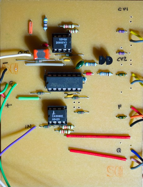
Can you upload the full pcb size pic?
If I recall the 470nF at the output needs to be poly.
did checked the led oriontetion?
_________________
http://www.myspace.com/mgmtrance |
|
|
Back to top
|
|
|
LektroiD
Joined: Aug 23, 2008
Posts: 1019
Location: Scottish Borders
Audio files: 2
G2 patch files: 2
|
|
|
Back to top
|
|
|
isak
Joined: Dec 13, 2009
Posts: 847
Location: Israel
Audio files: 18
|
| Posted: Fri Jan 11, 2013 11:30 am Post subject:
|
|
|
LEDs need to be green, it's important.
Don't plugin nothing to the input, first let's check if it's working right.
the LEDs need to be off (not lighted) when the reso is all the way down CCW.
Is it like that?
If yes turn the F to 12 o'clock and slowly trund the reso CW the LEDs need to light after half way (12 o'clock) and fully lighted when turning the reso all the way.
In this way it suppose to self osc.
Please try that and report back.
_________________
http://www.myspace.com/mgmtrance |
|
|
Back to top
|
|
|
LektroiD
Joined: Aug 23, 2008
Posts: 1019
Location: Scottish Borders
Audio files: 2
G2 patch files: 2
|
| Posted: Fri Jan 11, 2013 5:03 pm Post subject:
|
|
|
Green LEDs are in, but I can't do any more tests for two weeks, as I'm away. They only lit when a source was plugged into the output. I'm wondering if I popped the transistors too when I fed it with inverted power...
_________________
LektroiD |
|
|
Back to top
|
|
|
mrkva

Joined: Jan 25, 2012
Posts: 41
Location: poland/slovakia/netherlands
|
| Posted: Sun Apr 06, 2014 3:34 pm Post subject:
|
|
|
Hey guys,
maybe you can help me out. I've built myself the same circuit.
Filter part is working without issues, but resonance acts weird. It get very resonant around 1 o'clock and higher, and only in high frequencies. Maybe like just 3-5kHz. LEDs are lightning up in high resonances. I used same values as in the circuit, except the frequency pot which is not 47k but 100k - shouldn't matter right?
Thanks for any help/info |
|
|
Back to top
|
|
|
|

 Forum index » DIY Hardware and Software