| Author |
Message |
inlifeindeath

Joined: Apr 02, 2010
Posts: 316
Location: Albuquerque, NM
|
|
|
Back to top
|
|
 |
Tim Servo

Joined: Jul 16, 2006
Posts: 924
Location: Silicon Valley
Audio files: 11
|
 Posted: Thu May 09, 2013 4:51 pm Post subject:
An Analog Synthesizer for the 21st Century Posted: Thu May 09, 2013 4:51 pm Post subject:
An Analog Synthesizer for the 21st Century |
  |
|
| chieffrancis wrote: | There's this little protrusion at the edge of my potentiometers that is preventing me from mounting it flat onto the panel..
Does anyone know what this protrusion's purpose is or how to prevent it from affecting the positioning? |
That little protrusion is meant to go in a smaller hole in the front panel, and is meant to help keep the pot from rotating and lossening up the mount nuts. They are very rarely used from what I've seen, and generally can be broken off as suggested above.
Tim (I hate it when my nuts get loose) Servo |
|
|
Back to top
|
|
|
chieffrancis
Joined: Feb 07, 2013
Posts: 88
Location: california, united states
|
|
|
Back to top
|
|
|
chieffrancis
Joined: Feb 07, 2013
Posts: 88
Location: california, united states
|
| Posted: Thu May 09, 2013 5:28 pm Post subject:
|
|
|
Here's another question coming straight for youuuuuuuuuu!
When grounding all my boards, they can each be grounded by being attached to my steel panels right? As in, each module is grounded by it's own panel?

Can I straight up solder a bus wire from ground to anywhere on the panel?
Will the jacks and pots be affected from this since they're connected to the panel via washers/nuts? Or does this add to the ground (hopefully)? |
|
|
Back to top
|
|
|
elmegil

Joined: Mar 20, 2012
Posts: 2179
Location: Chicago
Audio files: 16
|
| Posted: Thu May 09, 2013 5:46 pm Post subject:
|
|
|
Break it off with a pair of stout pliers. The metal is soft.
I believe it's meant to be slotted in a hole to stop the pot from rotating, however, I've never seen a synth panel made to accomodate that kind of use. The general advice is break it off.
Edit: That's what I get for not paying attention to the fact that there's another page with responses already :/ |
|
|
Back to top
|
|
|
chieffrancis
Joined: Feb 07, 2013
Posts: 88
Location: california, united states
|
| Posted: Thu May 09, 2013 5:59 pm Post subject:
|
|
|
| elmegil wrote: |
Edit: That's what I get for not paying attention to the fact that there's another page with responses already :/ |
It's okay man, there's plenty of other unanswered questions to choose from  hahaha hahaha |
|
|
Back to top
|
|
|
elmegil
Joined: Mar 20, 2012
Posts: 2179
Location: Chicago
Audio files: 16
|
| Posted: Thu May 09, 2013 6:15 pm Post subject:
|
|
|
Transformers I try not to talk too much about because AC can be deadly and I don't know much.
As for the ground question, I don't normally see module panels getting explicit grounding; they do usually get their grounding from the nuts of the jacks. Power to boards usually still has an explicit ground wire (or two, or three). |
|
|
Back to top
|
|
|
chieffrancis
Joined: Feb 07, 2013
Posts: 88
Location: california, united states
|
| Posted: Thu May 09, 2013 8:03 pm Post subject:
|
|
|
hey elmegil,
just to verify, when connecting normally open jacks with my jacks, I skip out on using the middle (+15V in ADSR) connector right?
for example, as in the 1V/oct input on the xrvco, the top lug would go to ground and the bottom lug to the 100kohm? |
|
|
Back to top
|
|
|
State Machine
Janitor


Joined: Apr 17, 2006
Posts: 2810
Location: New York
Audio files: 24
|
| Posted: Thu May 09, 2013 8:33 pm Post subject:
|
|
|
Francis:
The schematic that you posted, is that the keyboard that you are going to use in this application? If so, I can let you know exactly how to hook it up to the IKC. Worst case is you may have to reverse all the diodes on the keyboard, then will be perfectly usable with having to spring for the Fatar keyboard. It looks like little work for big savings.
Bill |
|
|
Back to top
|
|
|
chieffrancis
Joined: Feb 07, 2013
Posts: 88
Location: california, united states
|
| Posted: Thu May 09, 2013 8:53 pm Post subject:
|
|
|
| State Machine wrote: | Francis:
The schematic that you posted, is that the keyboard that you are going to use in this application? If so, I can let you know exactly how to hook it up to the IKC. Worst case is you may have to reverse all the diodes on the keyboard, then will be perfectly usable with having to spring for the Fatar keyboard. It looks like little work for big savings.
Bill |
That isn't the keyboard I'm using, only a schematic someone used to reference me. The keyboard I'm using is the one I posted pictures of on the previous page.
It seems to have 8 column pins that are connected to the anodes of the diodes in the keyboard but the row pins seem to be connected to 14 pins.
I believe I can connect the 8 column pins directly to the molex column inputs on the IKC but the rows pins are where I'm stumped as it has 14 rather than the 8 pins available on the IKC.
The schematic I was referred to only has 5 row pins, although it is only for a 37 key whereas mine is a 49 key. |
|
|
Back to top
|
|
|
State Machine
Janitor
Joined: Apr 17, 2006
Posts: 2810
Location: New York
Audio files: 24
|
| Posted: Thu May 09, 2013 8:59 pm Post subject:
|
|
|
Ok I took a close look and if this is indeed the schematic of your keyboard, all you need to do to get it to interface to the IKC is to swap rows with columns. The signals labels C0 to C7 on you schematic are the lines that get driven which are the Rows outputs On the IKC.
IKC. R0 R1 R2 R3 R4 R5 R6 R7
MFOS C0 C1 C2 C3 C4 C5 C6 C7
IKC. C0 C1 C2 C3 C4
MFOS. R0 R1 R2 R3 R4 |
|
|
Back to top
|
|
|
State Machine
Janitor
Joined: Apr 17, 2006
Posts: 2810
Location: New York
Audio files: 24
|
| Posted: Thu May 09, 2013 9:01 pm Post subject:
|
|
|
Ok , then try the swap I explained in my previous post of it does not work. In fact of the COL pins are connected to diode anodes, then you definitely need to swap rows with columns. As stated, my ROW pins drive the matrix, not the columns
The last part of the mustery -- I will have to find out why there are 14 row pins.
Bill |
|
|
Back to top
|
|
|
elmegil
Joined: Mar 20, 2012
Posts: 2179
Location: Chicago
Audio files: 16
|
| Posted: Thu May 09, 2013 9:21 pm Post subject:
|
|
|
| Right, if you're using switch jacks for standard jacks, you wire the ground (on the angle) and the tip only, not the middle one that goes to the switch. If you look at it, you should be able to see exactly what I mean. |
|
|
Back to top
|
|
|
chieffrancis
Joined: Feb 07, 2013
Posts: 88
Location: california, united states
|
| Posted: Thu May 09, 2013 9:47 pm Post subject:
|
|
|
| State Machine wrote: | Ok , then try the swap I explained in my previous post of it does not work. In fact of the COL pins are connected to diode anodes, then you definitely need to swap rows with columns. As stated, my ROW pins drive the matrix, not the columns
The last part of the mustery -- I will have to find out why there are 14 row pins.
Bill |
Are you saying that the diode anodes should be connected to the row inputs on the IKC? |
|
|
Back to top
|
|
|
State Machine
Janitor
Joined: Apr 17, 2006
Posts: 2810
Location: New York
Audio files: 24
|
| Posted: Fri May 10, 2013 5:50 am Post subject:
|
|
|
I am saying that my ROW signals are actually OUTPUTS. Thus, they will drive the matrix. My IKC COL signals then do the reading. This, in turn, allows the IKC to generate its key code for analog conversion and MIDI NOTE number.
If you say the your keyboard COL signals are connected to diode anodes, connecting the COL inputs on the IKC will never work.
Clear as mud.
LOL! !!  |
|
|
Back to top
|
|
|
State Machine
Janitor
Joined: Apr 17, 2006
Posts: 2810
Location: New York
Audio files: 24
|
|
|
Back to top
|
|
|
chieffrancis
Joined: Feb 07, 2013
Posts: 88
Location: california, united states
|
| Posted: Fri May 10, 2013 10:46 am Post subject:
|
|
|
i decided i'm just gonna cave and drive to santa monica for a bare 5 oct fatar keyboard..
this is coming wayyy too close to the wire ahah
i'd love to figure it out for the future projects however.
any tips on connecting the 5 oct keyboard to the ikc bill?
thanks for your help |
|
|
Back to top
|
|
|
State Machine
Janitor
Joined: Apr 17, 2006
Posts: 2810
Location: New York
Audio files: 24
|
| Posted: Sat May 11, 2013 8:30 am Post subject:
|
|
|
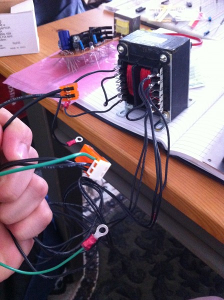
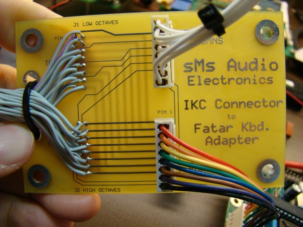
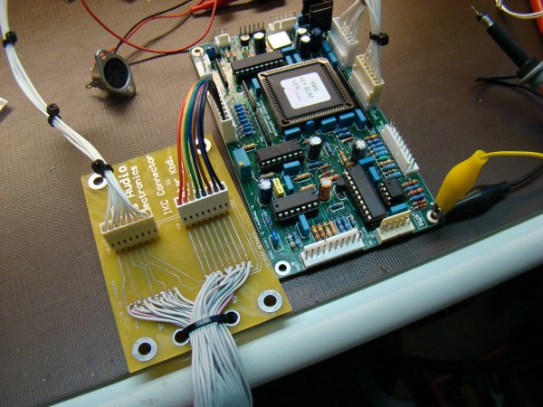
Page 51 and 52 of the build manual enplanes exactly how to connect a 5 octave Fatar keyboard to the IKC. I have a breakout board that will make this really easy and between this and the instructions you should be good to go !!! PM your address and I will ship one out to you man ASAP. I have attached some pictures of what it looks like.
As you can see from the pictures, the ROW and COL connectors connect to the IKC, following my directions, one end of each of the two Fatar connectors are removed and soldered to the adapter board and then strain relieved with a wire tie.
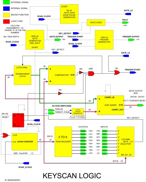
Use the matrix schematic to understand the hookup and connector pin assignments and it will become very clear. The IKC ROWS drives the T0 thru T7 lines and the the IKC COL read the MK lines (make contact of the Fatar) .... do not use the BK lines (fatar break contact). The schematic in the manual shows these connections.
I think you should be set on this.
Bill
| Description: |
|
| Filesize: |
1.15 MB |
| Viewed: |
307 Time(s) |
| This image has been reduced to fit the page. Click on it to enlarge. |
|
| Description: |
|
| Filesize: |
1000.99 KB |
| Viewed: |
269 Time(s) |
| This image has been reduced to fit the page. Click on it to enlarge. |
|
| Description: |
|
| Filesize: |
1.05 MB |
| Viewed: |
322 Time(s) |
| This image has been reduced to fit the page. Click on it to enlarge. |
|
| Description: |
|
| Filesize: |
64.08 KB |
| Viewed: |
307 Time(s) |
| This image has been reduced to fit the page. Click on it to enlarge. |
|
|
|
|
Back to top
|
|
|
chieffrancis
Joined: Feb 07, 2013
Posts: 88
Location: california, united states
|
| Posted: Sat May 11, 2013 6:08 pm Post subject:
|
|
|
hey bill i had a question about the jumpers.
"Place a shorting jumper, Digikey PN S9001-ND, on J12 to allow the MIDI data to pass to the output. Place another jumper across COM and PD on J6 if using the MCC display board or driving the MIDI address inputs into J3 from a logic device or microcontroller. If using switches, then place a jumper across the COM and PU pin on J6 to provide a pull up voltage and ground reference for the switches. In some instances though, the pull down connection may be required depending on the type of switches you use such as thumbwheel types."
not sure what you mean by using switches. just need a little clarification on that.
also, the longer leads of the jumpers go to the board? i'm just confused by this because if i put the longer leads in first, the jumpers don't fit on the smaller leads on the component side of the pcb.. |
|
|
Back to top
|
|
|
chieffrancis
Joined: Feb 07, 2013
Posts: 88
Location: california, united states
|
| Posted: Sat May 11, 2013 6:47 pm Post subject:
|
|
|
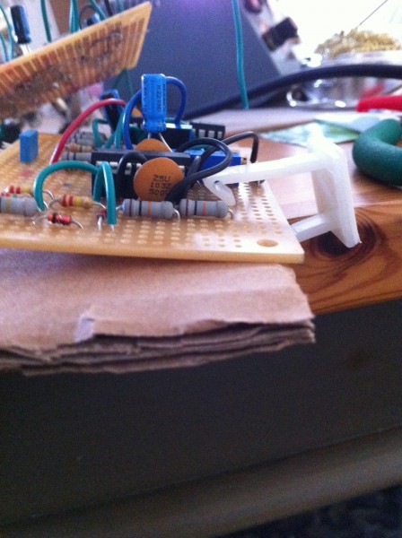
i had a question guys (i start way too many posts with this).
is it okay if i use cardboard underneath my perfboards (have cardboard in contact with the leads/solder/etc.) in order to physically stabilize them when i insert them into wire clips as so in the pictures?
also, when connecting multiple perfboards, should i have the wires coming up and over (since they will be vertically stacked) or should i just have them come up straight? i think straight would look much neater but i'm not sure if the leads coming out the top end of the perfboard is a safe thing to do..
thanks!
| Description: |
|
| Filesize: |
1.96 MB |
| Viewed: |
281 Time(s) |
| This image has been reduced to fit the page. Click on it to enlarge. |
|
| Description: |
|
| Filesize: |
2.11 MB |
| Viewed: |
299 Time(s) |
| This image has been reduced to fit the page. Click on it to enlarge. |
|
|
|
|
Back to top
|
|
|
elmegil
Joined: Mar 20, 2012
Posts: 2179
Location: Chicago
Audio files: 16
|
| Posted: Sun May 12, 2013 4:51 am Post subject:
|
|
|
Cardboard is non-conducting, so I don't see why it should be a problem on the bottom of the board. The only hazard I can think of is if it was in contact with things that would heat up. You should probably test your boards before you put them in contact with cardboard .
Also not sure I understand what you mean by "up and over" versus "up straight". |
|
|
Back to top
|
|
|
State Machine
Janitor
Joined: Apr 17, 2006
Posts: 2810
Location: New York
Audio files: 24
|
| Posted: Sun May 12, 2013 8:22 am Post subject:
|
|
|
| Quote: | hey bill i had a question about the jumpers.
"Place a shorting jumper, Digikey PN S9001-ND, on J12 to allow the MIDI data to pass to the output. Place another jumper across COM and PD on J6 if using the MCC display board or driving the MIDI address inputs into J3 from a logic device or microcontroller. If using switches, then place a jumper across the COM and PU pin on J6 to provide a pull up voltage and ground reference for the switches. In some instances though, the pull down connection may be required depending on the type of switches you use such as thumbwheel types."
not sure what you mean by using switches. just need a little clarification on that.
also, the longer leads of the jumpers go to the board? i'm just confused by this because if i put the longer leads in first, the jumpers don't fit on the smaller leads on the component side of the pcb..
|
If you plan on using the MIDI function, the channel number that you communicate on needs to be entered via a 4 bit input code to the IKC. If you did not have a midi channel changer board, of which you do have one, then you would need to wire up 4 switches to enter the MIDI data. This can be DIP or discrete switches on a front panel. I personally think the midi changer board I sent you is much more elegant and has a very nice digital display showing the MIDI channel number.
I am not sure what you mean when you mention leads for jumpers. I am talking about header jumpers that are inserted on the PCB.
Hope this clears things a bit for you.
Bill |
|
|
Back to top
|
|
|
chieffrancis
Joined: Feb 07, 2013
Posts: 88
Location: california, united states
|
| Posted: Sun May 12, 2013 12:09 pm Post subject:
|
|
|
| State Machine wrote: | | Quote: | hey bill i had a question about the jumpers.
"Place a shorting jumper, Digikey PN S9001-ND, on J12 to allow the MIDI data to pass to the output. Place another jumper across COM and PD on J6 if using the MCC display board or driving the MIDI address inputs into J3 from a logic device or microcontroller. If using switches, then place a jumper across the COM and PU pin on J6 to provide a pull up voltage and ground reference for the switches. In some instances though, the pull down connection may be required depending on the type of switches you use such as thumbwheel types."
not sure what you mean by using switches. just need a little clarification on that.
also, the longer leads of the jumpers go to the board? i'm just confused by this because if i put the longer leads in first, the jumpers don't fit on the smaller leads on the component side of the pcb..
|
If you plan on using the MIDI function, the channel number that you communicate on needs to be entered via a 4 bit input code to the IKC. If you did not have a midi channel changer board, of which you do have one, then you would need to wire up 4 switches to enter the MIDI data. This can be DIP or discrete switches on a front panel. I personally think the midi changer board I sent you is much more elegant and has a very nice digital display showing the MIDI channel number.
I am not sure what you mean when you mention leads for jumpers. I am talking about header jumpers that are inserted on the PCB.
Hope this clears things a bit for you.
Bill |
I see. I meant which side of the header goes into the PCB first, the longer leads? Subsequently, to which laeds of the headers are the shorting jumpers attached? |
|
|
Back to top
|
|
|
State Machine
Janitor
Joined: Apr 17, 2006
Posts: 2810
Location: New York
Audio files: 24
|
| Posted: Sun May 12, 2013 1:23 pm Post subject:
|
|
|
| Quote: | | I see. I meant which side of the header goes into the PCB first, the longer leads? Subsequently, to which laeds of the headers are the shorting jumpers attached? |
Oh OK. The short lead inserts into the PCB.
Bill |
|
|
Back to top
|
|
|
chieffrancis
Joined: Feb 07, 2013
Posts: 88
Location: california, united states
|
| Posted: Mon May 13, 2013 6:57 am Post subject:
|
|
|
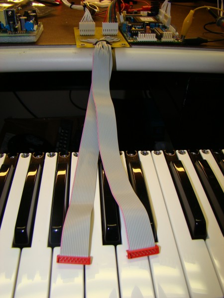
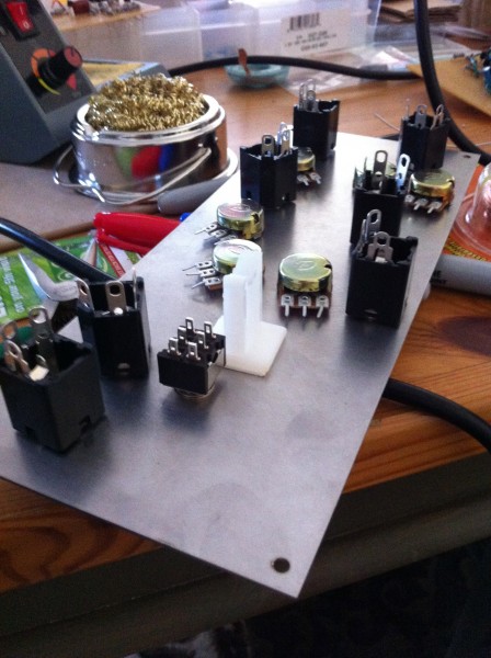
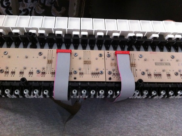
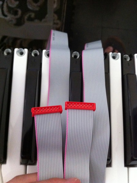
hey bill,
how can you tell which pin is which on the micromatch connectors?
here's how i have it:
do i have the pink wire at pin 1 or pin 16 on the fatar?
| Description: |
|
| Filesize: |
1.63 MB |
| Viewed: |
279 Time(s) |
| This image has been reduced to fit the page. Click on it to enlarge. |
|
| Description: |
|
| Filesize: |
2.04 MB |
| Viewed: |
295 Time(s) |
| This image has been reduced to fit the page. Click on it to enlarge. |
|
|
|
|
Back to top
|
|
|
|

 Forum index » DIY Hardware and Software » Thomas Henry designs